Portable GPS Tracker with Arduino
“As an Amazon Associates Program member, clicking on links may result in Maker Portal receiving a small commission that helps support future projects.”
In the past, we explored the NEO-6M GPS module with Arduino through a few of our tutorials (see: "Comparing iPhone GPS Against NEO-6M with Arduino" and "Arduino GPS Tracker"). In this tutorial, we wanted to push the size limits of the portable GPS tracker by using a mini GPS module called the ATGM336H. The result is a pocket-sized GPS tracker with the low-profile by pairing the ATGM336H module with an Arduino Xiao microcontroller, SD Card Module, and 3.7V LiPo Battery. The prototype developed here will be an autonomous tracker that will record latitude/longitude at roughly 1-10 points per second (1Hz - 10Hz) and needs no external components to track geolocation. The prototype can fit in a users pocket and can track for several hours. We will also present a Python program that will plot the geolocation data points that the user can use to view the route tracked by the Arduino GPS datalogger system. The Python analysis demonstrates how well the ATGM336H GPS module and antenna are able to replicate the walking path of a human with great resolution and accuracy.
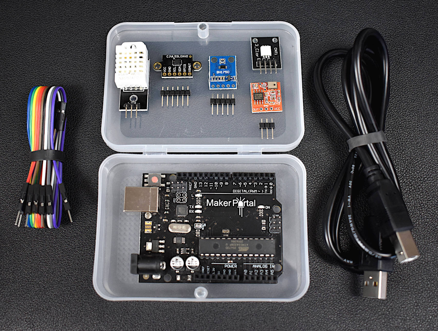
The components used in this tutorial are fairly straightforward. We need a GPS module, a microcontroller that can read the GPS data, an SD module for saving data, and finally a battery to power the portable prototype. We are also using one of our component boxes that is roughly the size of a smartphone or thicker wallet. We are also using very low-profile jumper wires to ensure that the height of the prototype stays within the component box, along with a mini breadboard. We are also using a Raspberry Pi 4 computer to interface with the Arduino board. All components are listed below:
Mini GPS Module + Antenna (ATGM336H) - $15.00 [Our Store]
Arduino Xiao (ATSAMD21) Microcontroller - $15.00 [Our Store]
SD Card Module - $8.00 [Our Store]
3.7V LiPo Battery Kit - $15.00 [Our Store]
Component Box - $3.00 [Our Store]
Mini Breadboard - $3.00 [Our Store]
Mini Jumper Wires - $10.49 (560pcs) [Amazon]
Raspberry Pi 4 Computer - $69.99 (4GB) [Amazon], $119.99 (8GB Kit) [Amazon]

The pinout for the Arduino Xiao board is given below as a reference before the full wiring diagram is shown:

ATSAMD21 Board Pinout Diagram
The SD module is wired to the Xiao via SPI (MISO, MOSI, SCK, etc.), while the ATGM336H GPS module is wired via serial (UART). The wiring diagram is given below, followed by the pinout wiring table:

The wiring table is given below for each component wired to the ATSAMD21 microcontroller:

Note the connection of the 3.7V LiPo battery to the 5V input. This ensures that the power give to the other modules is regulated down to 3.3V. We have also randomly chosen the CS pin for the SD module, any other available pin could be chosen for the chip select (CS). Similarly, the GPS serial TX/RX pins can be randomly selected, as long as they correspond to the pins defined in the Arduino software serial implementation. Below, we will be using the wiring given in the table above, so be sure to keep the wiring as outlined above when testing the codes in the next section.
The Arduino code used to acquire GPS data from the ATGM336H module requires the TinyGPSPlus library given at the link below:
https://github.com/mikalhart/TinyGPSPlus
To install the TinyGPSPlus library, clone it from the GitHub link above, unzip it, rename the folder to “TinyGPSPlus” and then move it to the “libraries” folder in your Arduino directory. This will make the GPS parser library available to the Arduino IDE, visible as “TinyGPS++” to the user.
Next, the user can navigate to the GitHub directory for this project:

The GitHub directory contains the datalogger code used to acquire and save GPS coordinates onto the SD card. The Arduino GPS datalogger code is given below for reference:
/***************************************************************************
* Arduino Xiao GPS Datalogger
* -- using ATGM336H + SD Module
*
*
*  by Josh Hrisko | Maker Portal LLC (c) 2021
*
*
***************************************************************************/
#include <SPI.h>
#include <SD.h>
#include <TinyGPS++.h>
#include <SoftwareSerial.h>

const int chipSelect = 6; // chip select for SD module
String filename = "gpsLog.csv"; // filename for saving to SD card

static const int RXPin = 2, TXPin = 1; // pins for ATGM336H GPS device
static const uint32_t GPSBaud = 9600; // default baudrate of ATGM336H GPS device

TinyGPSPlus gps;
SoftwareSerial ss(TXPin, RXPin);

void setup() {
  Serial.begin(9600); // start serial monitor for debugging
  ss.begin(GPSBaud);

  if (!SD.begin(chipSelect)) { // verify SD card and module are working
    Serial.println("SD Card not found");
    while (1);
  }

  if (SD.exists(filename)) {
    SD.remove(filename); // delete file if it already exists
  }

  data_saver("Date [mm/dd/yyyy], Time [HH:MM:SS.ZZ], Latitude [deg], Longitude [deg]"); // save data header

}

void loop() {
  while (ss.available() > 0){
    if (gps.encode(ss.read()) && gps.location.isValid() && gps.date.isValid() && gps.time.isValid()){
      String data_to_save = ""; // data string for saving
      data_to_save += String(gps.date.month())+"/"+String(gps.date.day())+"/"+
                      String(gps.date.year())+",";
      data_to_save += String(gps.time.hour())+":"+String(gps.time.minute())+":"+
                      String(gps.time.second())+"."+String(gps.time.centisecond())+",";
      data_to_save += String(gps.location.lat(),8)+","; // latitude
      data_to_save += String(gps.location.lng(),8); // longitude

      data_saver(data_to_save); // save new data points

//      Serial.println(data_to_save); // uncomment to print GPS data
    }
  }

}

void data_saver(String WriteData){ // data saver function
  File dataFile = SD.open(filename, FILE_WRITE); // open/create file
  if (dataFile) {
    dataFile.println(WriteData); // write data to file
    dataFile.close(); // close file before continuing
  } else {
    delay(50); // prevents cluttering
    Serial.println("SD Error"); // print error if SD card issue
  }

}
In the above code, we are first defining pin 6 as the chip select (CS) pin, as prescribed in the wiring diagram above. Second, the data filename is given as “gpsLog.csv” - there is a limit to the length of the filename, based on the SD library. So be sure to keep the filename as minimal as possible, and avoid using certain characters (we have had trouble in the past with underscores and long filenames).
Next, we are defining GPS module parameters, with pins 1/2 as the TX/RX pins, respectively. The baudrate is set as 9600, which is the default for the ATGM336H (in contrast to other modules that start at 4800).
Note: In the setup function we are deleting the old GPS log file. This should be commented out to append to the file or a routine should be developed that handles file creation dynamically to avoid deletion and overwriting.
The final line of the setup function creates a header that we can use to identify the data configuration once we open the file later for post processing. We expect the header and data configuration to be as described below:
"Date [mm/dd/yyyy], Time [HH:MM:SS.ZZ], Latitude [deg], Longitude [deg]"
This means we will have a data array saved as Date, Time, Latitude, Longitude. We are saving the data in comma-separated value (CSV) format, so we expect parsing of the data to be very simple.
It may also be of importance to note that once the system is powered on for the first time, it can take 30 seconds for the GPS module to fix to the required number of satellites and return a valid geolocation point. This may also be extended if the user is starting the module indoors or in a city with tall buildings.
A final note on the Arduino code: we are only using the basic components of geolocation, date, time, latitude, and longitude. The GPS library also allows users to access speed, altitude, directionality, and other parameters. So if the user wants to add those, they can do so in the main if() call in the void loop() function:
if (gps.encode(ss.read()) && gps.location.isValid() && gps.date.isValid() && gps.time.isValid()){
      String data_to_save = ""; // data string for saving
      data_to_save += String(gps.date.month())+"/"+String(gps.date.day())+"/"+
                      String(gps.date.year())+",";
      data_to_save += String(gps.time.hour())+":"+String(gps.time.minute())+":"+
                      String(gps.time.second())+"."+String(gps.time.centisecond())+",";
      data_to_save += String(gps.location.lat(),8)+","; // latitude
      data_to_save += String(gps.location.lng(),8); // longitude

      // add other parameters to data_to_save here...

      data_saver(data_to_save); // save new data points
    }

For our experiment, we walked up and down roughly 5 blocks along the streets of San Francisco. In the next section, we will see how well the GPS tracker was able to follow our path along the walk by implementing a Python csv reader algorithm that maps the coordinates to an open street map (OSM).
A popular geographic visualization toolbox called ‘cartopy’ will be used to plot the geographic coordinates onto the Google Open Street Map template. We previously wrote a blog post introduction to cartopy: “Geographic Visualizations in Python with Cartopy.” We will be jumping right into implementations with cartopy, so be sure to have the package installed and working before attempting to follow along below.
The first step is to take the GPSLOG.CSV file from the SD card and copy it into the local Python script folder. This will allow us to access it directly in the Python code. The full Python code is given below for reference, and it is also on the project’s GitHub page:
##################################################
#
# Mapping GPS data acquired by Arduino
# -- using cartopy to visualize lat/lon points
#
# by Joshua Hrisko | Maker Portal LLC (c) 2021
#
##################################################
#
#
import csv
import numpy as np
import cartopy.crs as ccrs
%matplotlib
import matplotlib.pyplot as plt
import cartopy.io.img_tiles as cimgt
from cartopy.mpl.ticker import LongitudeFormatter, LatitudeFormatter
import io,time
from urllib.request import urlopen, Request
from PIL import Image
plt.ion()

def image_spoof(self, tile): # this function pretends not to be a Python script
    url = self._image_url(tile) # get the url of the street map API
    req = Request(url) # start request
    req.add_header('User-agent','Anaconda 3') # add user agent to request
    fh = urlopen(req)
    im_data = io.BytesIO(fh.read()) # get image
    fh.close() # close url
    img = Image.open(im_data) # open image with PIL
    img = img.convert(self.desired_tile_form) # set image format
    return img, self.tileextent(tile), 'lower' # reformat for cartopy

################################
# parsing the GPS coordinates
################################
#
arduino_data = []
with open('GPSLOG.CSV','r') as dat_file:
    reader = csv.reader(dat_file)
    for row in reader:
        arduino_data.append(row)

header = arduino_data[0] # header text

date,time_vec,lats,lons = [],[],[],[]
for row in arduino_data[1:]:
    date.append(row[0])
    time_vec.append(row[1])
    lats.append(float(row[2]))
    lons.append(float(row[3]))

#######################################
# Formatting the Cartopy plot
#######################################
#
cimgt.GoogleTiles.get_image = image_spoof # reformat web request for street map spoofing
osm_img = cimgt.GoogleTiles() # spoofed, downloaded street map

fig = plt.figure(figsize=(14,12),facecolor='#FCFCFC') # open matplotlib figure
ax1 = plt.axes(projection=osm_img.crs) # project using coordinate reference system (CRS) of street map
ax1.set_title('Arduino GPS Tracker Map',fontsize=16)
lat_zoom = 0.001 # zoom out from the bounds of lats
lon_zoom = 0.005 # zoom out from the bounds of lons
extent = [np.min(lons)-lon_zoom,np.max(lons)+lon_zoom,np.min(lats)-lat_zoom,np.max(lats)+lat_zoom] # map view bounds
ax1.set_extent(extent) # set extents
ax1.set_xticks(np.linspace(extent[0],extent[1],7),crs=ccrs.PlateCarree()) # set longitude indicators
ax1.set_yticks(np.linspace(extent[2],extent[3],7)[1:],crs=ccrs.PlateCarree()) # set latitude indicators
lon_formatter = LongitudeFormatter(number_format='0.1f',degree_symbol='',dateline_direction_label=True) # format lons
lat_formatter = LatitudeFormatter(number_format='0.1f',degree_symbol='') # format lats
ax1.xaxis.set_major_formatter(lon_formatter) # set lons
ax1.yaxis.set_major_formatter(lat_formatter) # set lats
ax1.xaxis.set_tick_params(labelsize=14)
ax1.yaxis.set_tick_params(labelsize=14)

scale = np.ceil(-np.sqrt(2)*np.log(np.divide((extent[1]-extent[0])/2.0,350.0))) # empirical solve for scale based on zoom
scale = (scale<20) and scale or 19 # scale cannot be larger than 19
ax1.add_image(osm_img, int(scale+1)) # add OSM with zoom specification

#######################################
# Plot the GPS points
#######################################
#

for ii in range(0,len(lons),10):
    ax1.plot(lons[ii],lats[ii], markersize=10,marker='o',linestyle='',
             color='#b30909',transform=ccrs.PlateCarree(),label='GPS Point') # plot points
    transform = ccrs.PlateCarree()._as_mpl_transform(ax1) # set transform for annotations

    plt.pause(0.001) # pause between point plots
The code above will technically animate the GPS points onto a street map. The final plot should look similar to the one below:

Running the script should result in an animation similar to the one shown below, which “walks” through the points in steps of 10 (to speed things up):
GPS Tracker Map Animation
In our case, the tracking was very accurate, to within a few feet. The specification of the ATGM336H GPS module is within 2.5m, so we are well within that limit. A few notes on the performance and expectations:
The Arduino code saves data points at an unspecified rate. This means that we may get 10 points at one moment, and 1 at another moment.
In our case, we were surrounded by buildings, so there is more fluctuation than there would likely be in a more open space.
When going from outdoors to indoors, things can fluctuate quite a bit due to interference.
We are using a small antenna for the ATGM336H (to keep the geometry minimal). The antenna can also be replaced with the larger square ceramic antennas (the ones commonly shipped with NEO-6M modules). We hypothesize that this will result in better performance overall, at the trade-off of larger geometry and weight.
We noticed that when starting the system indoors, it took quite a bit of time to get a reliable signal. However, once the signal was established, even after restarting the system, it was able to re-connect to the satellites and return valid coordinates fairly quickly.

The ATGM336H mini GPS module was demonstrated here as an alternative to the larger NEO-6M module and proved to be a competitive choice for a lower profile GPS tracker with Arduino. The ATGM336H worked nicely with the TinyGPS++ library and had no trouble tracking our walking path at fairly high temporal and spatial resolution. The goal of this project was to prototype a GPS tracker that can fit inside a regular pants pocket with widely available components. Using the ATGM336H, an ATSAMD21 microcontroller, SD module, and LiPo battery, we were able to achieve this. Of course, this is just the prototype phase and the system could be shrunk down to half its current size, if not smaller than that! We image that realistically, a tracker like this can fit in a form factor of a smartwatch or even smaller. We were able to prototype with the aforementioned components and plot them to verify the accuracy of the GPS tracker, all while it was placed inside our pocket. In just a few minutes, users can replicate this project and have a modular GPS tracker in the palm of their hand!
See more in Arduino: