Multi-Touch Sensor and Arduino
Skin contains several electrically conductive elements that permit the flow of electricity through animal bodies (for in-depth reasoning, read this academic paper). This phenomenon is the primary reason why electric shock is so dangerous to living things, and is the primary reason behind electrical safety in everyday human life. The conductive nature of skin also enables humans to employ resistive and capacitive sensing in technology. For example, most modern smart phones register a change in capacitance from a finger touch, which then carries out a specific task. In this experiment, I will touching an exposed wire that is connected to a voltage comparator. This will result in a HIGH value on a digital pin of the Arduino board, indicating a touch has occurred.
Video 1 below shows the conductivity of human skin. Notice that when the leads are in open air or touching the wood, the resistance reading on the multimeter is overloaded (which indicates not enough electricity is flow between them). Conversely, when the leads are touching a finger, but not each other, the multimeter reads a resistance, albeit a large one of several MegaOhms, indicating that electric is flowing between the leads. Video 2 below shows the output from the touch sensor (KY-036, find one here, or in a kit here). Notice that when the exposed wire is touched, the voltage reads upwards of 2 V. This causes the Arduino to register an interrupt on the digital pin, indicating the sensor has been touched.
Video 1: Human skin is slightly conductive, which enables the multimeter to read a value for resistance. This is in opposition to the conductivity of the air or the wood, which both show overflow - indicating that the resistance of both are too high to read.
Video 2: The touch sensor (KY-036) uses a voltage comparator to compare two voltages and returns the higher voltage. This means that when a conducting object touches the exposed wire, the sensor returns a value of around 2-3 V. This trips an Arduino (if wired as such) and results in a HIGH value on the pin.
Wiring and Arduino Code
The steps for wiring this project are very straightforward. Below in Figure 1 is the wiring diagram. This experiment uses a very simple digital pin wiring scheme. There is only one digital output, so I have wired it to pin D2 on the Uno board. The LEDs can also be wired in any way to any digital pin (or even analog pin for variable brightness).
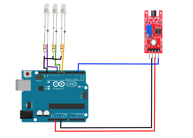
Figure 1: Wiring diagram for the touch sensor. The three LEDs can be wired to any pin, so long as they are marked as outputs. As for the output of the sensor, feel free to select any digital pin to designate as an input for the D0 of the KY-036 sensor.
byte touch_sense = 2; // designate input pin

// This is where you designate your LED pins
byte led_red = 8;
byte led_green = 9;
byte led_blue = 10;

// These variables are for timing purposes
int kk = 1;int time_out = 1;
bool state_on = 0;

void setup() {
  // initialize serial communication at 9600 bits per second:
  Serial.begin(9600);
  // make the touch sensor pin an input:
  pinMode(touch_sense, INPUT);
  // make the LEDs outputs:
  pinMode(led_red,OUTPUT);
  pinMode(led_green,OUTPUT);
  pinMode(led_blue,OUTPUT);
  // pre-define LEDs as off
  digitalWrite(led_red,LOW);
  digitalWrite(led_green,LOW);
  digitalWrite(led_blue,LOW);
}

void loop() {
  time_out++; // iterate
  int touch_state = digitalRead(touch_sense);
  Serial.print(touch_state);
  // if statement asking how many times it has been triggered:
  if (touch_state==1 and state_on == 0) {
    kk++;
    state_on = 1;
    time_out = 1;
    delay(50);
  } else if (state_on==1 and touch_state == 0) {
    state_on = 0;
    delay(50);
  }
  if (time_out>40){ // change this to change how quickly the touch sensor must be touched to register changes
    Serial.println(" ");
    Serial.println(kk);
    if (kk==2){
      // red on for 1 click
      digitalWrite(led_red,HIGH);
      digitalWrite(led_green,LOW);
      digitalWrite(led_blue,LOW);
    } else if (kk==3){
      // green on for 2 clicks
      digitalWrite(led_green,HIGH);
      digitalWrite(led_blue,LOW);
      digitalWrite(led_red,LOW);
    } else if (kk==4){
      // blue on for 3 clicks
      digitalWrite(led_blue,HIGH);
      digitalWrite(led_green,LOW);
      digitalWrite(led_red,LOW);
    } // if you want to improve this code, shorten it, or add more LEDs -- I recommend using an array. I did not do that here.
    kk = 1;
    time_out = 1;
    delay(10);
  }
  //Serial.println(touch_state); // uncomment if you want to view the state
  delay(2); // short pause between reads
}
Conclusion and Discussion
This was a fairly short tutorial because of the simplicity of the wiring and the sensor. If I were to build this sensor from scratch, it would be somewhat didactic and call for more elaboration on the electrical side of things, however, with the low cost of these sensors, I see no need here. I wanted to take the classic touch sensor and spice it up a bit (with the three different touches and the different LEDs), and even with the simplicity of things this particular projects has many applications. For example, you could build a classic touch lamp with this method. You could use the different speeds of touch to alter the brightness of the lamp. Another application could be in controlling your music player: you could use one touch to turn the music on and off, two touches to turn the volume up, three touches turns the volume down, etc.
The difficulty in this project lies in the code. Above, I used a time-out of 400 ms, which means if the user touched the sensor once in 400 ms, then only the red light will show. If the user manages to touch the sensor three times in 400 ms, then the blue will show. I also made the decision to limit the touches, so if the user touches the sensor more than 3 times, nothing happens. The code above has a lot of flexibility depending on the desired application. One could raise the timeout, or increase the number of possible states (touches within the timeout period), or even use the analog signal from the KY-036 to vary the tasks depending on amplitude. This was a short project that I thought would be educational and fun for anyone interesting in touch sensing and timeout states.
Products from our Shop relevant to this project:


See more in Arduino: