Posts tagged LED
WS2812 LED Ring Light with Raspberry Pi Pico

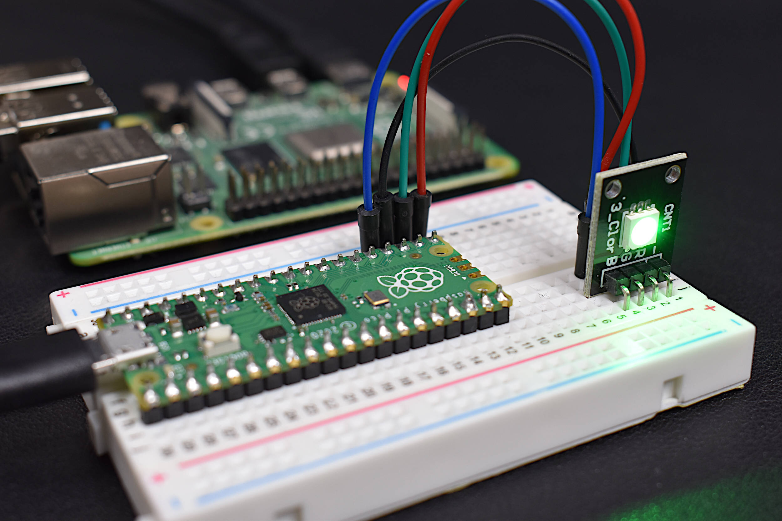
This is the second entry into the Raspberry Pi Pico tutorial series dedicated to exploring the capabilities of the Raspberry Pi Foundation's groundbreaking new Pico microcontroller. A WS2812 RGB LED is controlled via the programmable I/O system (PIO) on the Pico microcontroller. The code and methods used to control the WS2812 are based on Raspberry Pi Pico Micropython SDK the project entitled "Using PIO to drive a set of NeoPixel Ring (WS2812 LEDs)." A state machine is used on the Pico to control the WS2812 LED array, which allows users to test a range of algorithms that affect the ring light. The light mappings will subsequently be capable of emulating the LED effects similar to those demonstrated by the Amazon Alexa or Google Home devices. A universal wiring diagram is given that allows for any number of LEDs to be wired to the Pico, which we tested up to 60 LEDs.

Read More
An Introduction to the Raspberry Pi Pico with MicroPython

The Raspberry Pi Pico was recently released by the Raspberry Pi Foundation as a competitive microcontroller in the open-source electronics sphere. The Pico shares many of the capabilities of common Arduino boards including: analog-to-digital conversion (12-bit ADC), UART, SPI, I2C, PWM, among others. The board is just 21mm x 51mm in size, making it ideal for applications that require low-profile designs. One of the innovations of the Pico is the dual-core processor, which permits multiprocessing at clock rates up to 133 MHz. One particular draw of the Pico is its compatibility with MicroPython, which is chosen as the programming tool for this project. The focus on MicroPython, as opposed to C/C++, minimizes the confusion and time required to get started with the Pico. A Raspberry Pi 4 computer is ideal for interfacing with the Pico, which can be used to prepare, debug, and program the Pico. From start to finish - this tutorial helps users run their first custom MicroPython script on the Pico in just a few minutes. An RGB LED will be used to demonstrate general purpose input/output of the Pico microcontroller.

Read More
DIY Arduino Board

A DIY Arduino board is presented here, with most of the capabilities of the classic Arduino Uno board, but with a slimmer profile and more flexibility in hardware. The advantage to using the DIY Arduino board is its ability to change the input voltage (2.7V - 5.5V), the crystal oscillator (0-16MHz), and the use of LEDs and regulators when needed. The DIY board is capable of very lower power modes, without the requirement of draining components such as LEDs or regulators. The ATmega328P chip is at the center of every Uno board (in recent years), and is also at the center of the DIY board, which allows the DIY Arduino to behave almost identically to the Uno board.

Read More
Arduino Breathing LED Functions

In this tutorial - an Arduino board will be used in conjunction with an RGB LED to investigate several ways of replicating the breathing LED effect. Using the equation for a triangular wave, circular wave, and Gaussian wave, a breathing LED will be constructed. The amount of code needed for the simplest breathing LED is as little as two lines of code, while the more complex breathing functions grow in difficulty from there.

Read More
Controlling Arduino Pins from the Serial Monitor

In this tutorial, another method of control is introduced that involves manual control using input from the serial monitor. This means each pin can be turned on or off using the human input to the serial monitor. An RGB LED is used to demonstrate the capability of serial monitor control, where each color of the LED is controlled individually using dedicated Arduino pins.

Read More
Arduino Optical Fingerprint Sensor (AS608)

Optical fingerprint sensors take low-resolution snapshots of the tip of a finger and create arrays of identifiers that are then used to uniquely identify a given fingerprint. The AS608 is capable of storing up to 128 individual fingerprints. This tutorial will introduce the AS608 Arduino-compatible fingerprint sensor and how to validate and reject fingerprints based on the enrolled fingerprint information that will be given to the sensor. The fingerprint algorithm is handled by the AS608 and Arduino, so this tutorial will focus on implementation and putting the pieces together to make a working fingerprint sensor with Arduino.

Read More
Arduino Interrupts with PIR Motion Sensor

The basics of Arduino’s hardware interrupt is explored through the use of a passive infrared (PIR) sensor. The passive infrared sensors used here operate at voltages from 2.7V - 5V and use very little energy when operating in the non-tripped state. The PIR sensor is ultimately tripped by an infrared source, typically human body heat (or another animal with similar radiative emission). When the PIR sensor is tripped it sends a HIGH signal to its OUT pin, which will be read by the Arduino’s interrupt pin (pin 2 or 3 on the Uno board). This process seems trivial, but when done correctly can save massive amounts of energy when dealing with battery-powered systems, as in home automation.

Read More
Controlling LEDs with A Multiplexer and Arduino

A demultiplexer will be used to control 8 LEDs using just 3 digital pins on the Arduino board. This method of demultiplexing frees up pins on the Arduino, but also makes control of multiple LEDs easier by consolidating the power given to each LED. This will allow us to use LEDs without resistors. In general, a demultiplexer uses N boolean outputs to control 2N switches. In our case, the CD4051 multiplexer will be used as a demultiplexer using 3 digital pins and boolean logic to control 8 individual LEDs. Several skills will also be developed, specifically with regard to programming in the Arduino programming language. Pulse-width modulation (or brightening and dimming) of LEDs will be explored, as well as randomization of LED blinks, along with the general selection process for boolean switching with the demultiplexer.

Read More
A Guide to Metal Core PCBs by PCBGOGO

The use of LED based electronics has significantly increased in the past few years. They have proven to be more efficient and nearly 5 times cheaper than normal incandescent units. But with their use came one downside: heat. Some devices tend to use a number of LEDs that remain on for a long period of time and so can overheat. The LEDs are usually mounted on PCBs and can therefore cause significant damage. There is however one alternative to common PCBs i.e. metal core printed circuits (MCPCBs).

Read More
4-Pin RGB LED Control Using iOS BLExAR App, HM-10 Bluetooth Module, and Arduino

Control an RGB LED using three PWM pins on an Arduino Uno board via Bluetooth communication. An RGB LED is a single casing with three cathode (or anode) pins and one anode (or cathode) pin. This results in a 4-pin LED. In this tutorial, I will be using an RGB LED with three anodes and one common cathode. This means that we can change the color of the LED to over 16.7 million different variations (assuming each anode produces a different luminosity for each voltage change of the Arduino PWM pin). This tutorial will help demonstrate the power of the BLExAR app, and the flexibility of an Arduino board under iOS Bluetooth control. In my case, I will be using an iPhone with the BLExAR app, but an iPad would suffice as well.

Read More