WS2812 LED Ring Light with Raspberry Pi Pico
“As an Amazon Associates Program member, clicking on links may result in Maker Portal receiving a small commission that helps support future projects.”
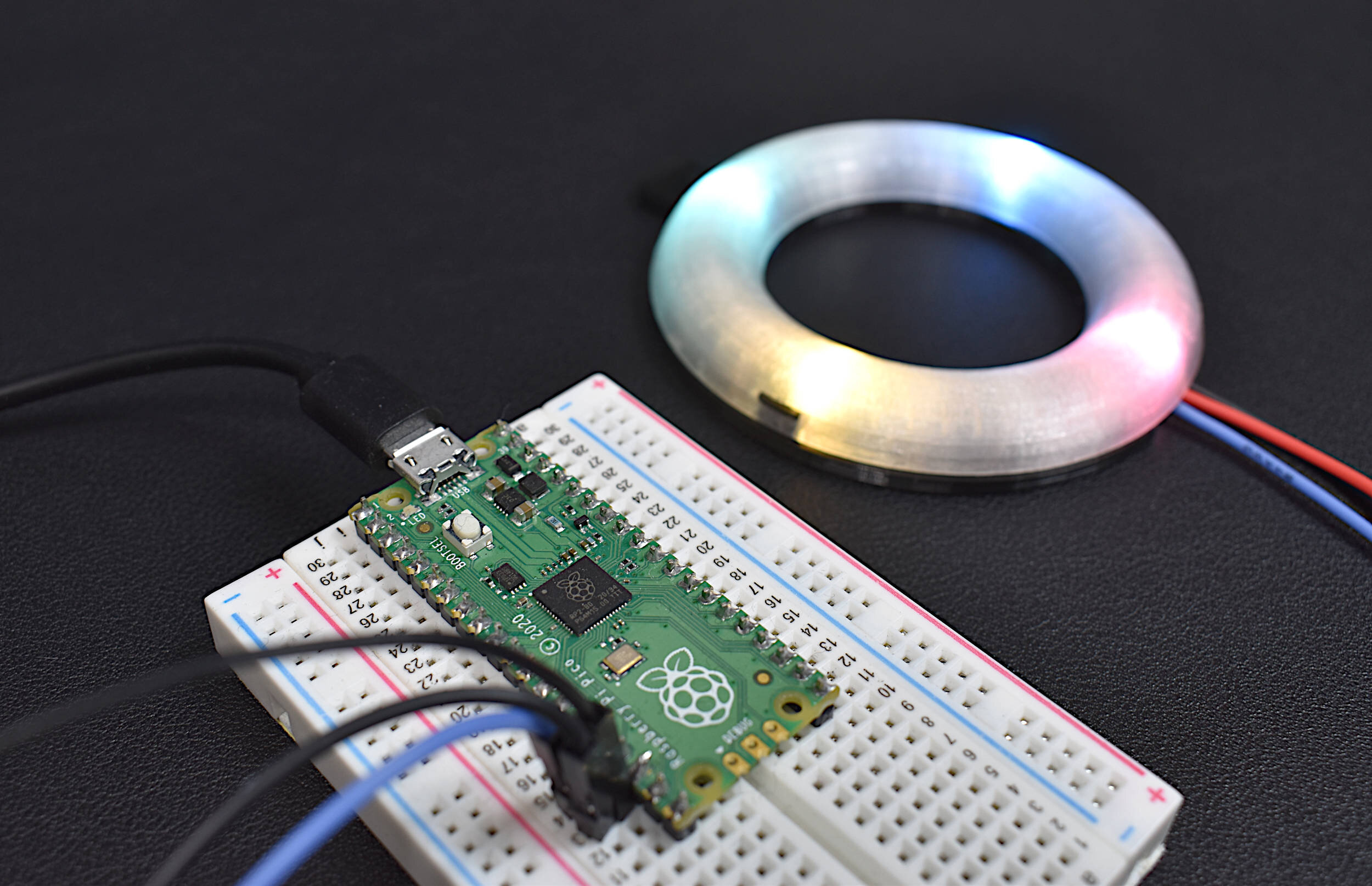
This is the second entry into the Raspberry Pi Pico tutorial series dedicated to exploring the capabilities of the Raspberry Pi Foundation's groundbreaking new Pico microcontroller. The first entry contains many of the 'getting started' essentials required to interface with the Raspberry Pi Pico, and thus, it is recommended that new users return to Part I before continuing with this project. In this second entry, a WS2812 RGB LED is controlled via the programmable I/O system (PIO) on the Pico microcontroller. The code and methods used to control the WS2812 are based on Raspberry Pi Pico Micropython SDK the project entitled "Using PIO to drive a set of NeoPixel Ring (WS2812 LEDs)." A state machine is used on the Pico to control the WS2812 LED array, which allows users to test a range of algorithms that affect the ring light. The light mappings will subsequently be capable of emulating the LED effects similar to those demonstrated by the Amazon Alexa or Google Home devices. A universal wiring diagram is given that allows for any number of LEDs to be wired to the Pico, which we tested up to 60 LEDs.
A 16-pixel LED ring light is recommended when using just the Raspberry Pi Pico microcontroller. If a larger pixel LED ring light is used, then an external power supply should be used in order to reduce the load requirement from the USB port. This is why a general 5V external supply is used in the wiring diagram for this project - it will allow users to use nearly any LED ring light with any number of pixels (with some caveats related to addressing the pixels). The full list of components used in this tutorial are given below:
Raspberry Pi Pico Starter Kit - $15.00 [Our Store]
16-Pixel RGB LED Ring Light - $15.00 [Our Store]
5V 3A Power Supply - $9.99 [Amazon]
Raspberry Pi 4 Computer - $58.99 (2GB), $61.50 (4GB), $88.50 (8GB) [Amazon], $55.00 [2GB from Our Store]
Note that the 5V 3A supply was chosen to handle ring lights that contain up to 85 pixels (based on the measured maximum current of 35mA for each LED). We were able to test 60 LEDs with the 5V/3A power supply without issue.
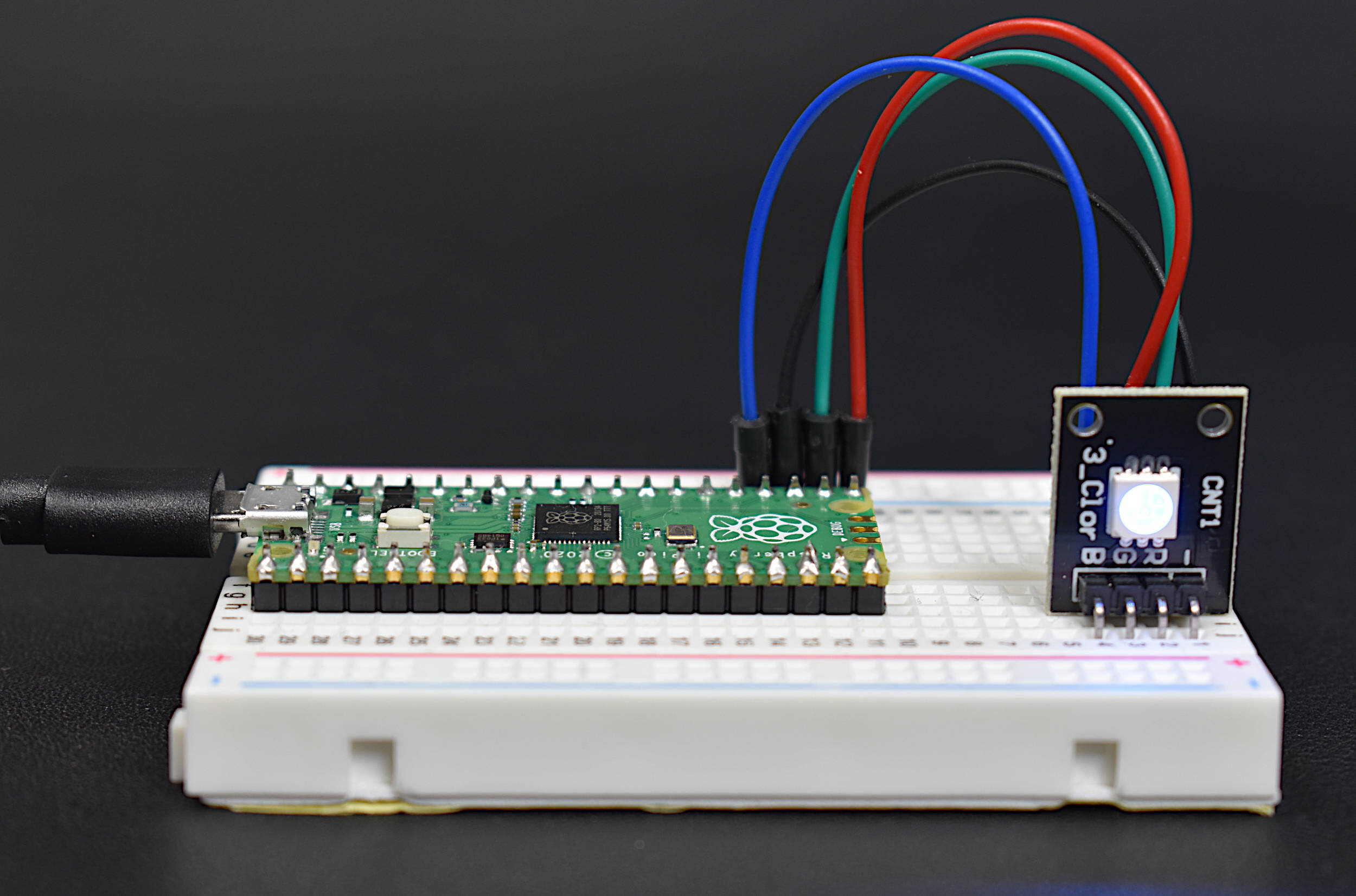
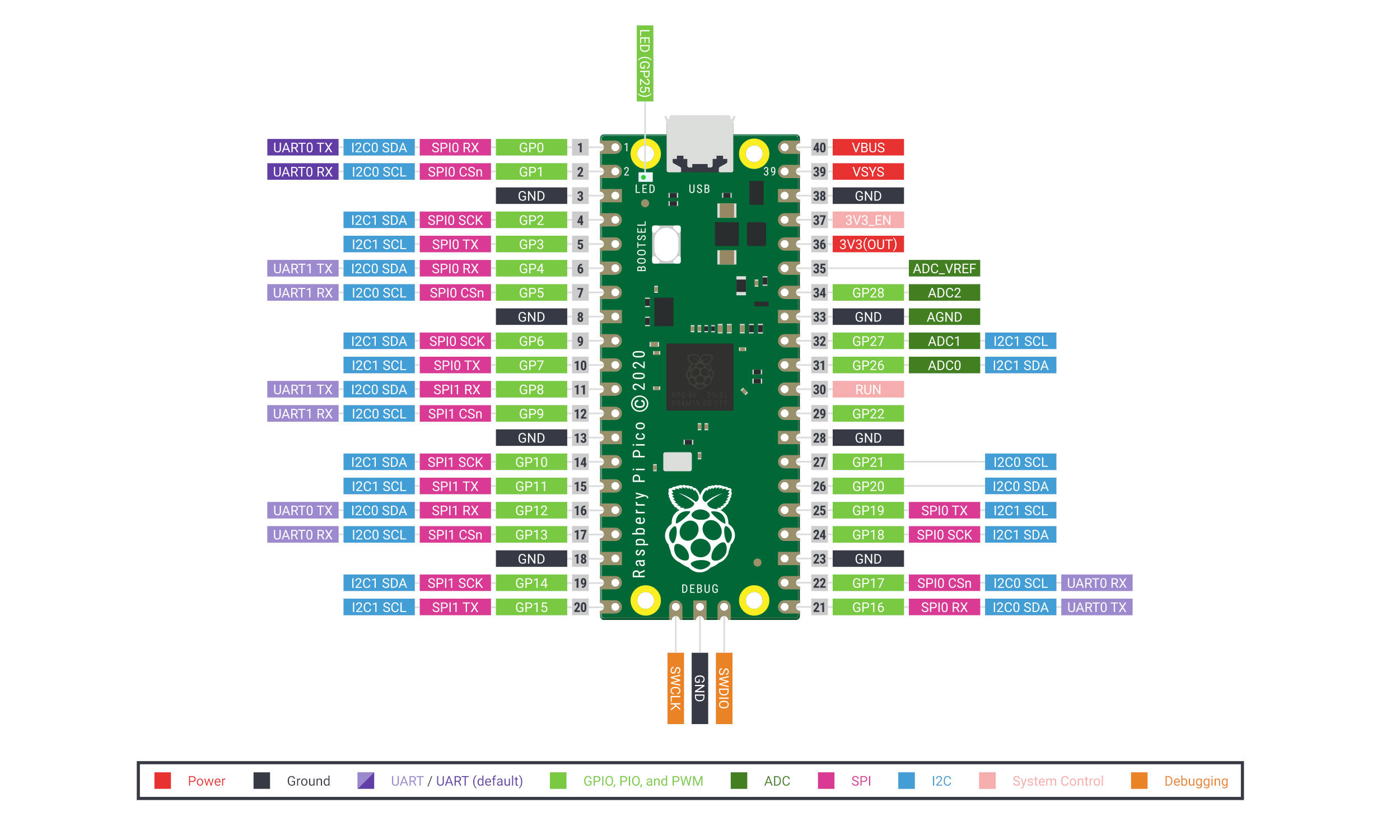
A pinout diagram for the Raspberry Pi Pico can be found here. The wiring diagram between the Raspberry Pi Pico and WS2812 RGB LED ring light is given below:
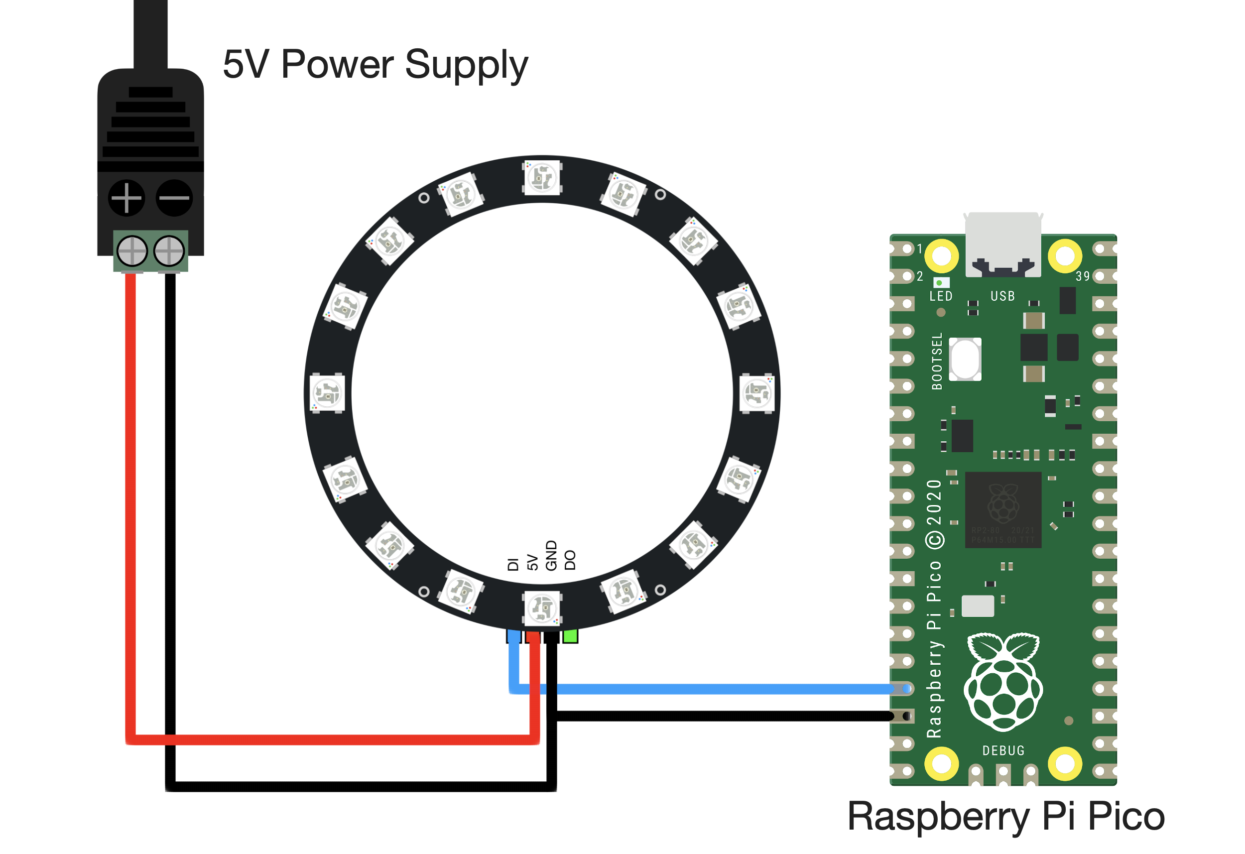
Note the use of the DI pin as the control pin for the WS2812 LED. The 5V is supplied by the external supply, and the Raspberry Pi, ring light, and external supply all share a ground. The DO pin on the ring light allows users to connect multiple assemblies of LEDs, but will not be used or discussed further in this tutorial. Technically, VBUS on the Pico (pin 40) is capable of supplying 0.5A (USB 2.0) or 1.0A (USB 3.0), thus, the 16-pixel LED ring light can be powered via the VBUS pin, however, it is safest to use either USB 3.0 or an external supply.
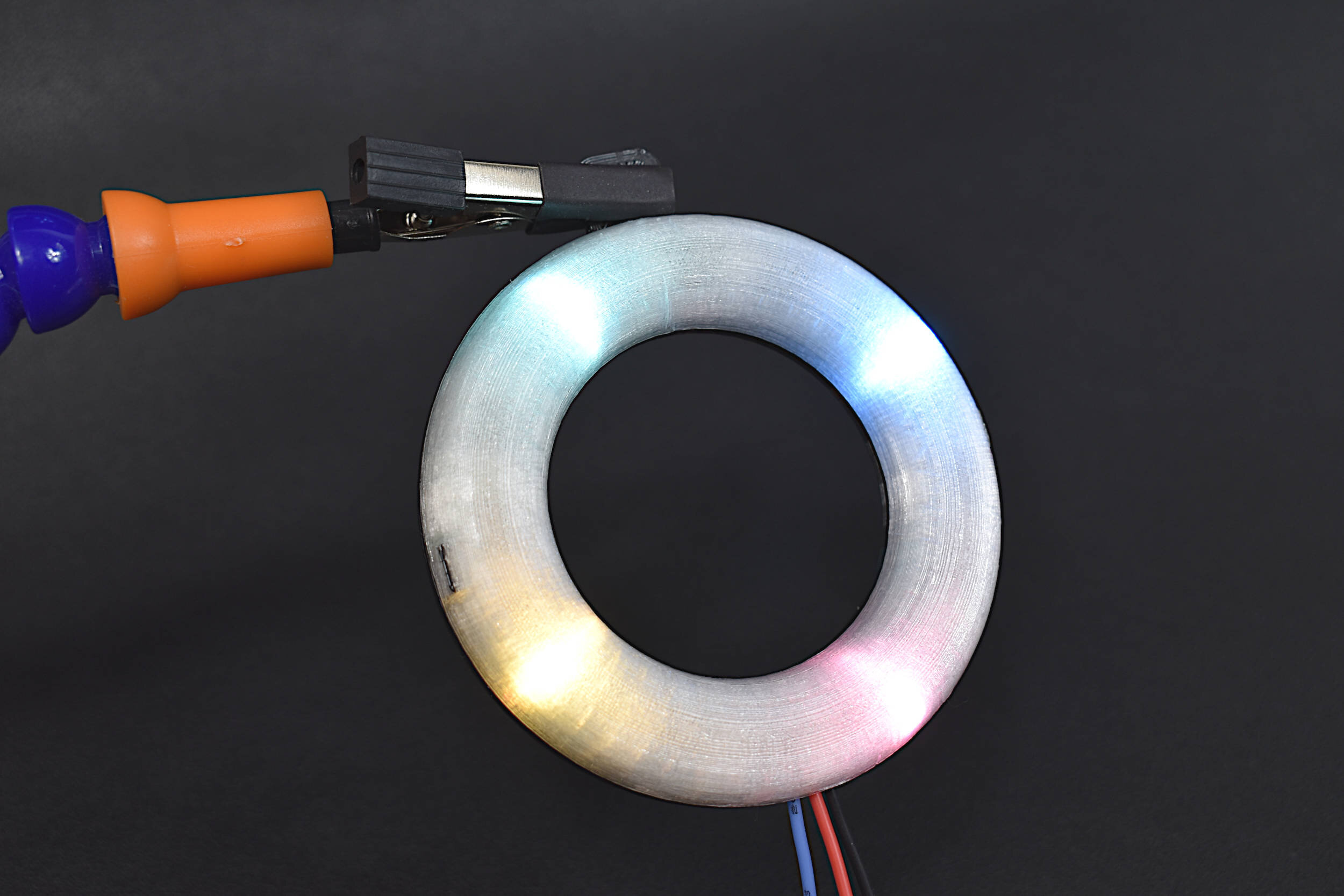
Below is a photo of the multimeter amperage output of the 16-Pixel LED Ring Light at maximum brightness for all 16 LEDs:

Based on the 0.55A measurement of the LED ring light at maximum brightness (shown above) — the average maximum for each LED is approximated as ≈35mA. In the next section, the MicroPython code framework for controlling the LEDs will be introduced along with a simple routine that creates a rotating pixel color. The Raspberry Pi Pico will be used along with Thonny to program the 16-Pixel Ring Light in real-time.
The 16-Pixel LED Ring Light will be controlled using the scheme outlined in the Raspberry Pi Pico MicroPython getting started document, where a tutorial entitled “Using PIO to drive a set of NeoPixel Ring (WS2812 LEDs)” contains a script that we will use to create a state machine on the RPi Pico. The state machine will be used to control the LEDs on the ring light using just a single pin on the Pico (GPIO13 as wired above). A full MicroPython example script can also be found at the Raspberry Pi Pico’s NeoPixel Ring repository on GitHub. Some of the algorithms that follow are not contained within that repository, but are included in the GitHub repository for this tutorial:

The code to start the state machine on the RPi Pico's GPIO pin #13 is given below:
import array, time
from machine import Pin
import rp2

#
############################################
# RP2040 PIO and Pin Configurations
############################################
#
# WS2812 LED Ring Configuration
led_count = 16 # number of LEDs in ring light
PIN_NUM = 13 # pin connected to ring light
brightness = 0.5 # 0.1 = darker, 1.0 = brightest

@rp2.asm_pio(sideset_init=rp2.PIO.OUT_LOW, out_shiftdir=rp2.PIO.SHIFT_LEFT,
             autopull=True, pull_thresh=24) # PIO configuration

# define WS2812 parameters
def ws2812():
    T1 = 2
    T2 = 5
    T3 = 3
    wrap_target()
    label("bitloop")
    out(x, 1)               .side(0)    [T3 - 1]
    jmp(not_x, "do_zero")   .side(1)    [T1 - 1]
    jmp("bitloop")          .side(1)    [T2 - 1]
    label("do_zero")
    nop()                   .side(0)    [T2 - 1]
    wrap()


# Create the StateMachine with the ws2812 program, outputting on pre-defined pin
# at the 8MHz frequency
state_mach = rp2.StateMachine(0, ws2812, freq=8_000_000, sideset_base=Pin(PIN_NUM))

# Activate the state machine
state_mach.active(1)
This snippet of code is the header for all algorithms to follow. The variable led_count = 16 states that we will be using a 16-pixel WS2812 LED ring light. PIN_NUM = 13 defines GPIO13 as our control pin, and brightness is used to dim the LEDs (1 = max brightness). The state_mach houses the state machine on GPIO13 at the allocations contained within ws2812. Finally, the last line in the code above activates the state machine and waits for changes to be implemented.
Another snippet of code is given below that loops a single color LED around the 16-pixel ring light:
###############################################################
# WS2812 RGB LED Ring Light Single-Pixel Loop
# with the Raspberry Pi Pico Microcontroller
#
# by Joshua Hrisko, Maker Portal LLC (c) 2021
#
# Based on the Example neopixel_ring at:
# https://github.com/raspberrypi/pico-micropython-examples
###############################################################
#
import array, time
from machine import Pin
import rp2

#
############################################
# RP2040 PIO and Pin Configurations
############################################
#
# WS2812 LED Ring Configuration
led_count = 16 # number of LEDs in ring light
PIN_NUM = 13 # pin connected to ring light
brightness = 0.5 # 0.1 = darker, 1.0 = brightest

@rp2.asm_pio(sideset_init=rp2.PIO.OUT_LOW, out_shiftdir=rp2.PIO.SHIFT_LEFT,
             autopull=True, pull_thresh=24) # PIO configuration

# define WS2812 parameters
def ws2812():
    T1 = 2
    T2 = 5
    T3 = 3
    wrap_target()
    label("bitloop")
    out(x, 1)               .side(0)    [T3 - 1]
    jmp(not_x, "do_zero")   .side(1)    [T1 - 1]
    jmp("bitloop")          .side(1)    [T2 - 1]
    label("do_zero")
    nop()                   .side(0)    [T2 - 1]
    wrap()


# Create the StateMachine with the ws2812 program, outputting on pre-defined pin
# at the 8MHz frequency
state_mach = rp2.StateMachine(0, ws2812, freq=8_000_000, sideset_base=Pin(PIN_NUM))

# Activate the state machine
state_mach.active(1)

# Range of LEDs stored in an array
pixel_array = array.array("I", [0 for _ in range(led_count)])
#
############################################
# Functions for RGB Coloring
############################################
#
def update_pix(brightness_input=brightness): # dimming colors and updating state machine (state_mach)
    dimmer_array = array.array("I", [0 for _ in range(led_count)])
    for ii,cc in enumerate(pixel_array):
        r = int(((cc >> 8) & 0xFF) * brightness_input) # 8-bit red dimmed to brightness
        g = int(((cc >> 16) & 0xFF) * brightness_input) # 8-bit green dimmed to brightness
        b = int((cc & 0xFF) * brightness_input) # 8-bit blue dimmed to brightness
        dimmer_array[ii] = (g<<16) + (r<<8) + b # 24-bit color dimmed to brightness
    state_mach.put(dimmer_array, 8) # update the state machine with new colors
    time.sleep_ms(10)

def set_24bit(ii, color): # set colors to 24-bit format inside pixel_array
    pixel_array[ii] = (color[1]<<16) + (color[0]<<8) + color[2] # set 24-bit color

#
############################################
# Main Loops and Calls
############################################
#
color = (255,0,0) # looping color
blank = (255,255,255) # color for other pixels
cycles = 5 # number of times to cycle 360-degrees
for ii in range(int(cycles*len(pixel_array))+1):
    for jj in range(len(pixel_array)):
        if jj==int(ii%led_count): # in case we go over number of pixels in array
            set_24bit(jj,color) # color and loop a single pixel
        else:
            set_24bit(jj,blank) # turn others off
    update_pix() # update pixel colors
    time.sleep(0.05) # wait 50ms
Below is a video demonstration of the code above, showing the single looping LED:

Single LED Loop with 16-Pixel Ring Light
The above is one of the simpler routines that we can do with the 16-pixel ring light.
Another fairly simple algorithm that we can try is a ‘breathing’ type LED routine that entails going from minimum to maximum brightness and back to minimum brightness. This results in a light-based ‘breathing’ that looks similar to some of those employed by the Amazon Alexa devices. The code is given below followed by another GIF demonstration:
###############################################################
# WS2812 RGB LED Ring Light Breathing
# with the Raspberry Pi Pico Microcontroller
#
# by Joshua Hrisko, Maker Portal LLC (c) 2021
#
# Based on the Example neopixel_ring at:
# https://github.com/raspberrypi/pico-micropython-examples
###############################################################
#
import array, time
from machine import Pin
import rp2

#
############################################
# RP2040 PIO and Pin Configurations
############################################
#
# WS2812 LED Ring Configuration
led_count = 16 # number of LEDs in ring light
PIN_NUM = 13 # pin connected to ring light
brightness = 1.0 # 0.1 = darker, 1.0 = brightest

@rp2.asm_pio(sideset_init=rp2.PIO.OUT_LOW, out_shiftdir=rp2.PIO.SHIFT_LEFT,
             autopull=True, pull_thresh=24) # PIO configuration

# define WS2812 parameters
def ws2812():
    T1 = 2
    T2 = 5
    T3 = 3
    wrap_target()
    label("bitloop")
    out(x, 1)               .side(0)    [T3 - 1]
    jmp(not_x, "do_zero")   .side(1)    [T1 - 1]
    jmp("bitloop")          .side(1)    [T2 - 1]
    label("do_zero")
    nop()                   .side(0)    [T2 - 1]
    wrap()


# Create the StateMachine with the ws2812 program, outputting on pre-defined pin
# at the 8MHz frequency
sm = rp2.StateMachine(0, ws2812, freq=8_000_000, sideset_base=Pin(PIN_NUM))

# Activate the state machine
sm.active(1)

# Range of LEDs stored in an array
ar = array.array("I", [0 for _ in range(led_count)])
#
############################################
# Functions for RGB Coloring
############################################
#
def pixels_show(brightness_input=brightness):
    dimmer_ar = array.array("I", [0 for _ in range(led_count)])
    for ii,cc in enumerate(ar):
        r = int(((cc >> 8) & 0xFF) * brightness_input) # 8-bit red dimmed to brightness
        g = int(((cc >> 16) & 0xFF) * brightness_input) # 8-bit green dimmed to brightness
        b = int((cc & 0xFF) * brightness_input) # 8-bit blue dimmed to brightness
        dimmer_ar[ii] = (g<<16) + (r<<8) + b # 24-bit color dimmed to brightness
    sm.put(dimmer_ar, 8) # update the state machine with new colors
    time.sleep_ms(10)

def pixels_set(i, color):
    ar[i] = (color[1]<<16) + (color[0]<<8) + color[2] # set 24-bit color

def breathing_led(color):
    step = 5
    breath_amps = [ii for ii in range(0,255,step)]
    breath_amps.extend([ii for ii in range(255,-1,-step)])
    for ii in breath_amps:
        for jj in range(len(ar)):
            pixels_set(jj, color) # show all colors
        pixels_show(ii/255)
        time.sleep(0.02)
#
############################################
# Main Calls and Loops
############################################
#
# color specifications
red = (255,0,0)
green = (0,255,0)
blue = (0,0,255)
yellow = (255,255,0)
cyan = (0,255,255)
white = (255,255,255)
blank = (0,0,0)
colors = [blue,yellow,cyan,red,green,white]

while True: # loop indefinitely
    for color in colors: # emulate breathing LED (similar to Amazon's Alexa)
        breathing_led(color)
        time.sleep(0.1) # wait between colors

WS2812 ‘Breathing’ LED
In the next section, a more in-depth example will be explored by creating a Google Home LED emulator.
At this point, the user should be comfortable with the functionality of the WS2812 LEDs and how to control the ring lights with the Pico state machine. In this section, we will be attempt to emulate the Google Home quad-LED rotating function, the Amazon Alexa’s rotating blue LED curve, and the Amazon Alexa’s zipped off function.
Below is the script used to carry out all three functions stated above:
###############################################################
# WS2812 RGB LED Ring Light
# Google Home and Amazon Alexa LED Emulator
# with the Raspberry Pi Pico Microcontroller
#
# by Joshua Hrisko, Maker Portal LLC (c) 2021
#
# Based on the Example neopixel_ring at:
# https://github.com/raspberrypi/pico-micropython-examples
###############################################################
#
import array, time
from machine import Pin
import rp2

#
############################################
# RP2040 PIO and Pin Configurations
############################################
#
# WS2812 LED Ring Configuration
led_count = 16 # number of LEDs in ring light
PIN_NUM = 13 # pin connected to ring light
brightness = 1.0 # 0.1 = darker, 1.0 = brightest

@rp2.asm_pio(sideset_init=rp2.PIO.OUT_LOW, out_shiftdir=rp2.PIO.SHIFT_LEFT,
             autopull=True, pull_thresh=24) # PIO configuration

# define WS2812 parameters
def ws2812():
    T1 = 2
    T2 = 5
    T3 = 3
    wrap_target()
    label("bitloop")
    out(x, 1)               .side(0)    [T3 - 1]
    jmp(not_x, "do_zero")   .side(1)    [T1 - 1]
    jmp("bitloop")          .side(1)    [T2 - 1]
    label("do_zero")
    nop()                   .side(0)    [T2 - 1]
    wrap()


# Create the StateMachine with the ws2812 program, outputting on pre-defined pin
# at the 8MHz frequency
state_mach = rp2.StateMachine(0, ws2812, freq=8_000_000, sideset_base=Pin(PIN_NUM))

# Activate the state machine
state_mach.active(1)

# Range of LEDs stored in an array
pixel_array = array.array("I", [0 for _ in range(led_count)])
#
############################################
# Functions for RGB Coloring
############################################
#
def update_pix(brightness_input=brightness): # dimming colors and updating state machine (state_mach)
    dimmer_array = array.array("I", [0 for _ in range(led_count)])
    for ii,cc in enumerate(pixel_array):
        r = int(((cc >> 8) & 0xFF) * brightness_input) # 8-bit red dimmed to brightness
        g = int(((cc >> 16) & 0xFF) * brightness_input) # 8-bit green dimmed to brightness
        b = int((cc & 0xFF) * brightness_input) # 8-bit blue dimmed to brightness
        dimmer_array[ii] = (g<<16) + (r<<8) + b # 24-bit color dimmed to brightness
    state_mach.put(dimmer_array, 8) # update the state machine with new colors
    time.sleep_ms(10)

def set_24bit(ii, color): # set colors to 24-bit format inside pixel_array
    color = hex_to_rgb(color)
    pixel_array[ii] = (color[1]<<16) + (color[0]<<8) + color[2] # set 24-bit color

def hex_to_rgb(hex_val):
    return tuple(int(hex_val.lstrip('#')[ii:ii+2],16) for ii in (0,2,4))
#
############################################
# Main Loops and Calls
############################################
#
# Create Google Home four color rotation scheme
google_colors = ['#4285f4','#ea4335','#fbbc05','#34a853'] # hex colors by Google
cycles = 5 # number of times to cycle 360-degrees
for jj in range(int(cycles*len(pixel_array))):
    for ii in range(len(pixel_array)):
        if ii%int(len(pixel_array)/4)==0: # 90-degree leds only
            set_24bit((ii+jj)%led_count,google_colors[int(ii/len(pixel_array)*4)])
        else:
            set_24bit((ii+jj)%led_count,'#000000') # other pixels blank
    update_pix() # update pixel colors
    time.sleep(0.05) # wait between changes

# Create Amazon Alexa rotation wheel
amazon_colors = ['#00dbdc','#0000d4'] # hex colors by Amazon
light_width = 3 # width of rotating led array
cycles = 3 # number of times width rotates 360-deg
for jj in range(int(cycles*len(pixel_array))):
    for ii in range(len(pixel_array)):
        if ii<light_width:
            set_24bit((ii+jj)%led_count,amazon_colors[0])
        else:
            set_24bit((ii+jj)%led_count,amazon_colors[1]) # other pixels blank
    update_pix() # update pixel colors
    time.sleep(0.03) # wait between changes
time.sleep(0.5)

# turn off LEDs using the Alexa zipper-type turnoff
for ii in range(int(len(pixel_array)/2)):
    set_24bit(ii,'#000000') # turn off positive side
    set_24bit(int(len(pixel_array)-ii-1),'#000000') # turn off negative side
    update_pix() # update
    time.sleep(0.02) # wait
In the code above, the user may notice that hex colors are being used as opposed to the RGB values from 0-255. This is simply due to the commonality of hex colors in brand colors. For Google we’re using four of their specified brand colors (taken from the Google.com logo):
These four colors will be placed 90-degrees from one another in order to emulate the Google Home LED display. If users are unaware of the Google Home LED routines, see this page for reference.
Below is a snippet of the code used to loop the four 90-degree LEDs to emulate the Google Home clockwise:
google_colors = ['#4285f4','#ea4335','#fbbc05','#34a853'] # hex colors by Google
cycles = 5 # number of times to cycle 360-degrees
for jj in range(int(cycles*len(pixel_array))):
    for ii in range(len(pixel_array)):
        if ii%int(len(pixel_array)/4)==0: # 90-degree leds only
            set_24bit((ii+jj)%led_count,google_colors[int(ii/len(pixel_array)*4)])
        else:
            set_24bit((ii+jj)%led_count,'#000000') # other pixels blank
    update_pix() # update pixel colors
    time.sleep(0.05) # wait between changes
Note that we are selecting only four LEDs and coloring them as the four Google colors. Then, we rotate them around the circle. To emulate the Alexa, we can use similar methods — all of which are given in the full code above and on the GitHub page for the project. Below is a snippet of the turnoff function used in Amazon Alexa devices, which is just a slight variation of the ‘chase’ style turnoff:
# turn off LEDs using the Alexa zipper-type turnoff
for ii in range(int(len(pixel_array)/2)):
    set_24bit(ii,'#000000') # turn off positive side
    set_24bit(int(len(pixel_array)-ii-1),'#000000') # turn off negative side
    update_pix() # update
    time.sleep(0.02) # wait
Below is a video demonstration of the Google and Amazon emulator created with the Raspberry Pi Pico and 16-pixel WS2812 ring light:
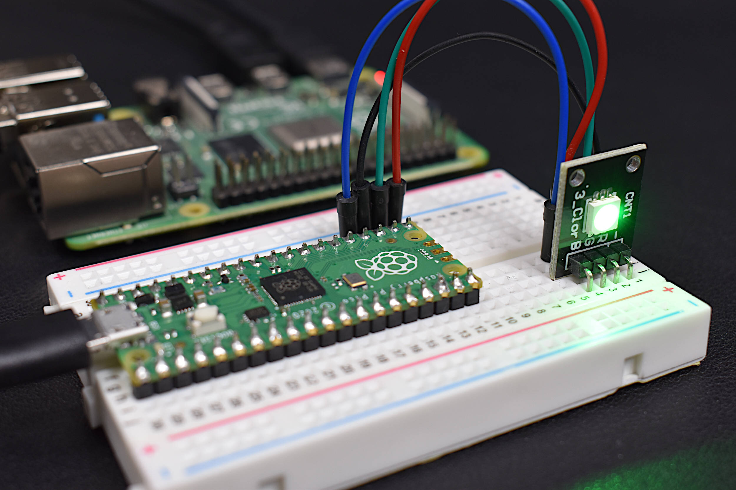
It is also noticeable that the LED colors do not quite match those depicted on computer screens. This is due to several reasons. First, the WS2812 LEDs are larger than display LEDs and the LEDs used in the Google Home and Amazon Alexa. This results in a less defined color where the red, blue, and green are more visible. Another reason for the color disparities is the use of the translucent dome, which may refract certain colors of light being emitted by the WS2812 LEDs.
In this second entry into the exploratory series of the Raspberry Pi Pico, a 16-Pixel RGB LED Ring Light was controlled using a state machine in MicroPython. Several different algorithms were outlined to emulate the Google Home color scheme, the Amazon Alexa LED schemes, and other unique color array methods. The LEDs used are similar to the widely available WS2812 RGB LEDs, which consume roughly 35mA each. The 16-pixel ring light was able to be safely powered via the VBUS pin on the Pico, which takes power directly from the USB 3.0 port on a Raspberry Pi 4 computer. This tutorial was meant as a further introduction to the Raspberry Pi Pico with MicroPython. This is only the second entry into a serial, where we focused on unique algorithms meant to push the limits of the Pico control of the ring light. This tutorial series will continue with further explorations of the Pico, with extensions into reading sensors, using different digital protocols such as UART, SPI, I2C, and other ways of testing the limits of the Pico microcontroller.

Zoomed-in view of a single RGB LED aboard the 16-pixel ring light.
See More in Raspberry Pi Pico and Microcontrollers:


