Raspberry Pi Stepper Motor Control with NEMA 17

“As an Amazon Associates Program member, clicking on links may result in Maker Portal receiving a small commission that helps support future projects.”
The NEMA 17 is a widely used class of stepper motor used in 3D printers, CNC machines, linear actuators, and other precision engineering applications where accuracy and stability are essential. The NEMA-17HS4023 is introduced here, which is a version of the NEMA 17 that has dimensions 42mm x 42mm x 23mm (Length x Width x Height). In this tutorial, the stepper motor is controlled by a DRV8825 driver wired to a Raspberry Pi 4 computer. The Raspberry Pi uses Python to control the motor using an open-source motor library. The wiring and interfacing between the NEMA 17 and Raspberry Pi is given, with an emphasis on the basics of stepper motors. The DRV8825 control parameters in the Python stepper library are broken down to educate users on how the varying of each parameter impacts the behavior of the NEMA 17. Simple characteristics of stepper control are explored: stepper directivity (clockwise and counterclockwise), step incrementing (full step, half step, micro-stepping, etc.), and step delay. As stated before, Python and a Raspberry Pi computer will be used as the control components for this project.
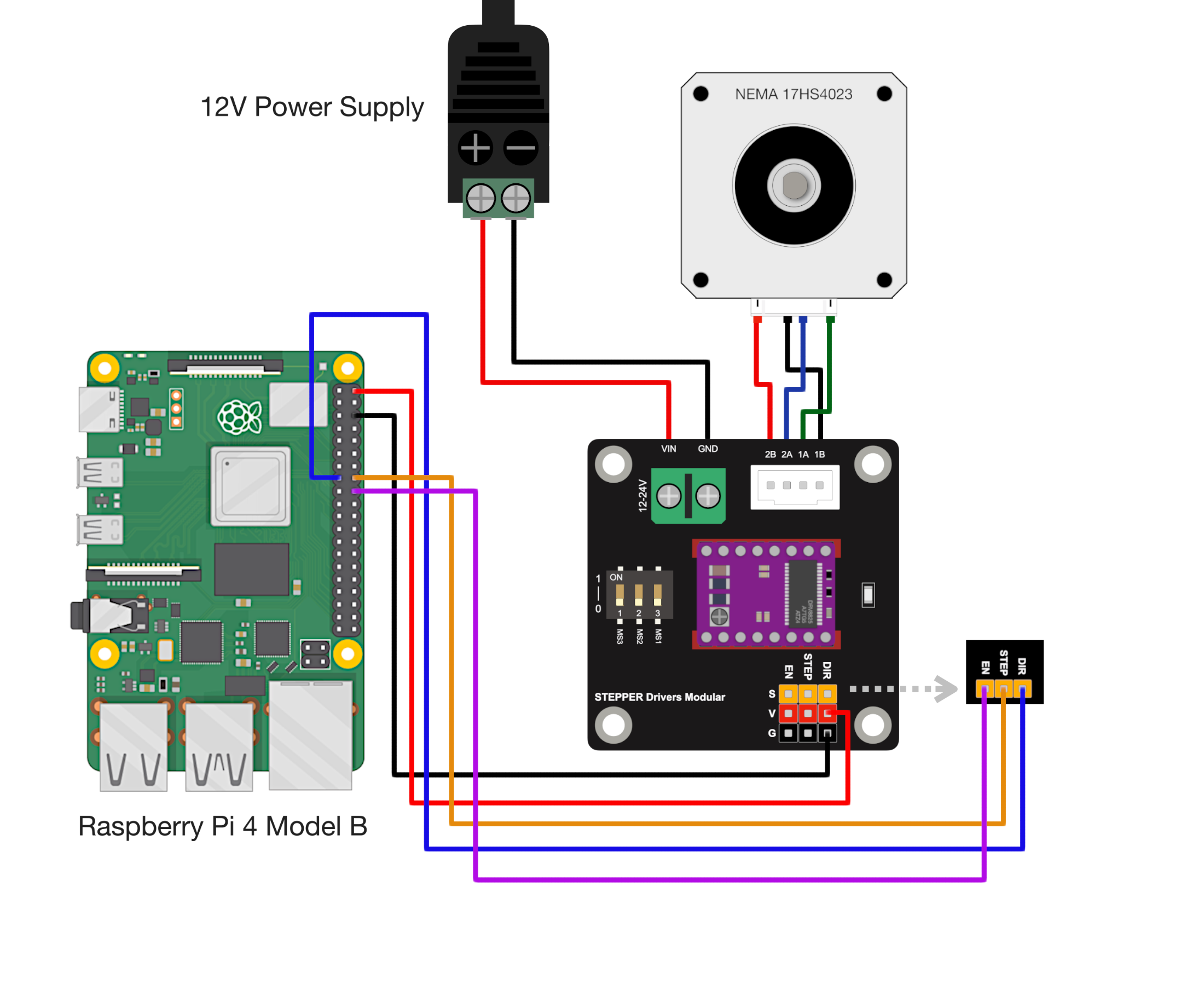
A NEMA 17 stepper motor (model: 17HS4023) is wired to a DRV8825 stepper controller, which is subsequently wired to a Raspberry Pi 4 Model B. The NEMA 17 HS4023 motor also requires a 12V power supply with at least 2 amps of current to operate at peak torque. The following parts list is the minimum for following along with this tutorial:

The DRV8825 is wired to the stepper controller, which has pinouts for the DIR, STEP, EN, VCC, and GND pins on the DRV8825. Thus, the wiring diagram for the stepper to the Raspberry Pi involves these five pins. The stepper controller must also have the 12V 2A power supply attached to its power terminal. Finally, the stepper motor (NEMA 17HS4023) has to be wired to the stepper bridge. The wiring diagram is given below:
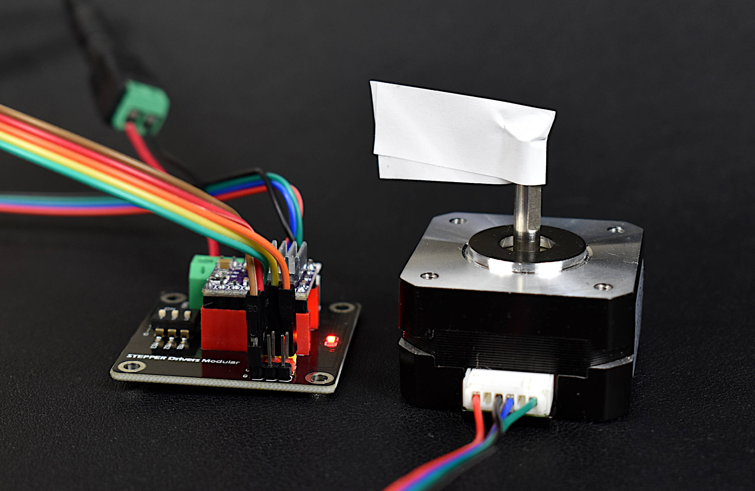
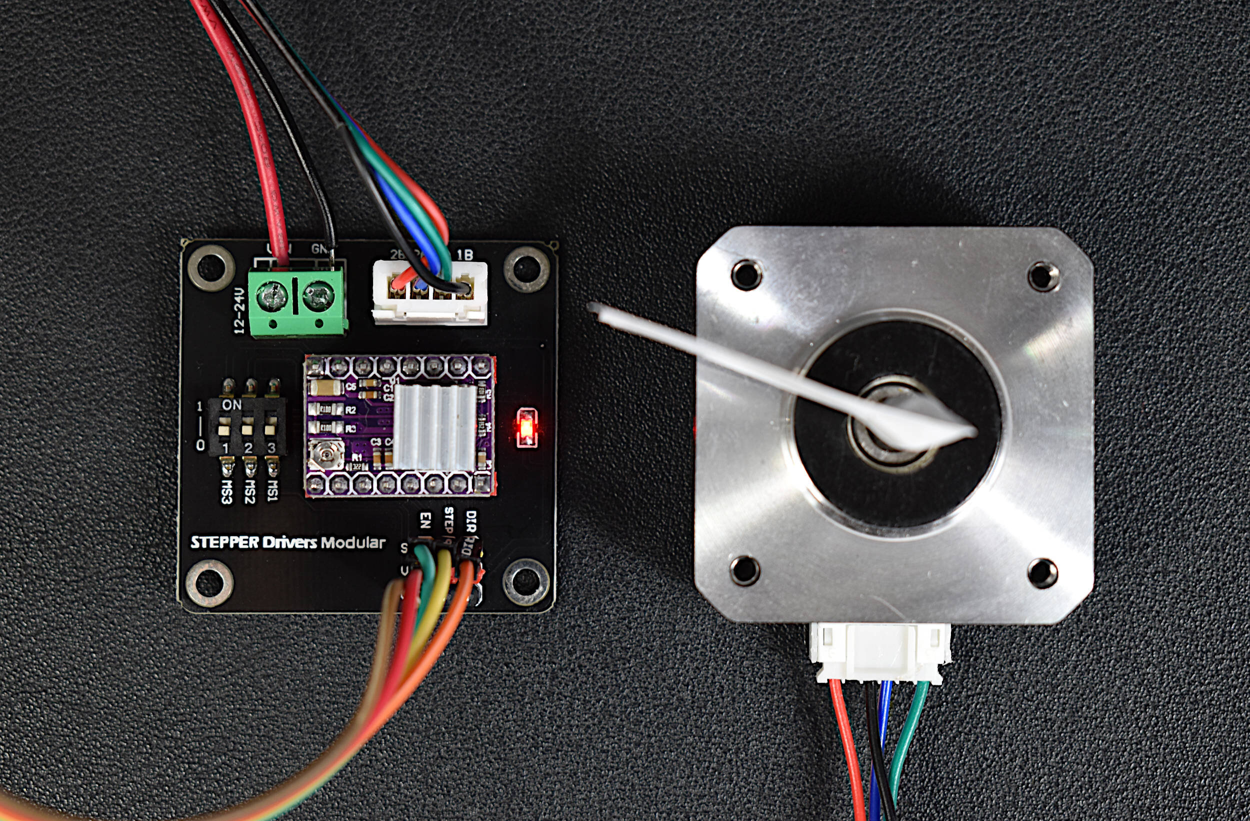
A photo of the NEMA 17 stepper, DRV8825 driver, and bridge are shown below:
A widely used Raspberry Pi motor library written by Gavin Lyons for Python can be found on GitHub: https://github.com/gavinlyonsrepo/RpiMotorLib. The RpiMotorLib library is compatible with a series of stepper and servo motors and drivers, including the NEMA17 and DRV8825 used here. The page that is particularly useful for this project is the readme file for the DRV8825: https://github.com/gavinlyonsrepo/RpiMotorLib/blob/master/Documentation/Nema11DRV8825.md. This document will be the basis for the Python library implementation going forward.
The easiest install for the RpiMotorLib uses pip:
pi@raspberrypi:~ $ sudo pip3 install rpimotorlib
The above assumes Python 3.x will be used for the stepper control, which is the case in this tutorial.
#######################################
# Copyright (c) 2021 Maker Portal LLC
# Author: Joshua Hrisko
#######################################
#
# NEMA 17 (17HS4023) Raspberry Pi Tests
# --- rotating the NEMA 17 to test
# --- wiring and motor functionality
#
#
#######################################
#
import RPi.GPIO as GPIO
from RpiMotorLib import RpiMotorLib
import time

################################
# RPi and Motor Pre-allocations
################################
#
#define GPIO pins
direction= 22 # Direction (DIR) GPIO Pin
step = 23 # Step GPIO Pin
EN_pin = 24 # enable pin (LOW to enable)

# Declare a instance of class pass GPIO pins numbers and the motor type
mymotortest = RpiMotorLib.A4988Nema(direction, step, (21,21,21), "DRV8825")
GPIO.setup(EN_pin,GPIO.OUT) # set enable pin as output

###########################
# Actual motor control
###########################
#
GPIO.output(EN_pin,GPIO.LOW) # pull enable to low to enable motor
mymotortest.motor_go(False, # True=Clockwise, False=Counter-Clockwise
                     "Full" , # Step type (Full,Half,1/4,1/8,1/16,1/32)
                     200, # number of steps
                     .0005, # step delay [sec]
                     False, # True = print verbose output
                     .05) # initial delay [sec]

GPIO.cleanup() # clear GPIO allocations after run
The code above spins the NEMA 17 motor 200 steps to cover a full 360° rotation, assuming the MS1-MS3 pins are all 0 (1.8 degrees per step).
Note: If the motor is not stepping or if the motor is getting to hot - the screw on the DRV8825 may need to be increased (clockwise) or decreased (counterclockwise) to control the current flowing to the stepper
The screw on the DRV8825 is shown below:
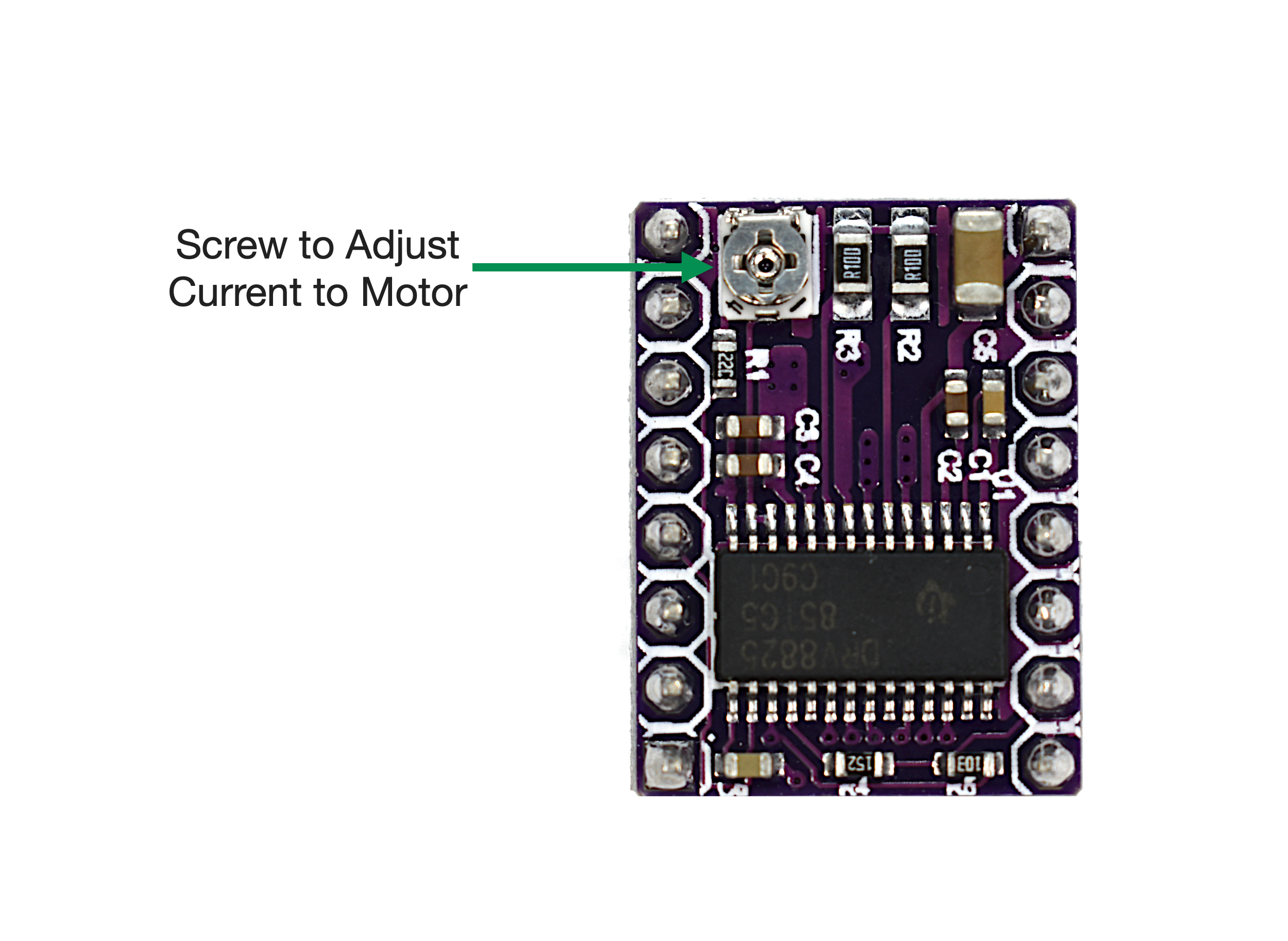
Another way to verify the current going to the NEMA 17 is to measure the current going from the screw block to ground (bottom right pin on the DRV8825 orientation above). There is a great tutorial on doing this for Arduino on makerguides.com. By placing a multimeter around the screw and ground and measuring voltage, the relationship between the voltage and current is approximately:

Another way of thinking of the equation above is: the voltage measured between the screw and ground relates to the current given to each phase of the stepper. And since the NEMA 17 (HS4023) has two phases, we can relate the current per phase to the measured voltage across the screw and ground, which makes conversion simple. The NEMA-17HS4023 stepper motor seems to have differing current ratings based on various datasheets (one example at datasheetspdf.com), however, it seems the current limit on the 17HS4023 seems to be between 0.7A-1.0A per phase. Thus, we can configure the voltage reading to be between 0.7V and 1.0V. When testing the voltage reference, make sure the enable pin (EN) is pulled to GND to enable the motor.
Below is a test rotation of 360° with the NEMA 17 using the code given above. For reference, the voltage readout from the DRV8825 was 0.9V, which is roughly 0.9A per phase. The stepper gets quite hot at this amperage, so for purposes where low torque is used, the current could be lowered a bit.

The motion of the NEMA 17 is specified in the motor_go() function above:
mymotortest.motor_go(False,"Full",200,0.0005,False,0.05)
The first argument, a boolean value, controls the clockwise (False) or counterclockwise (True) motion of the rotation.
The second argument, a string, controls the stepping increment based on the DRV8825 MS1-MS3 values (read about the specifics in the DRV8825 datasheet). The 0-1 value of each of the MS1-MS3 values controls the stepping increment following the specification in the table below:
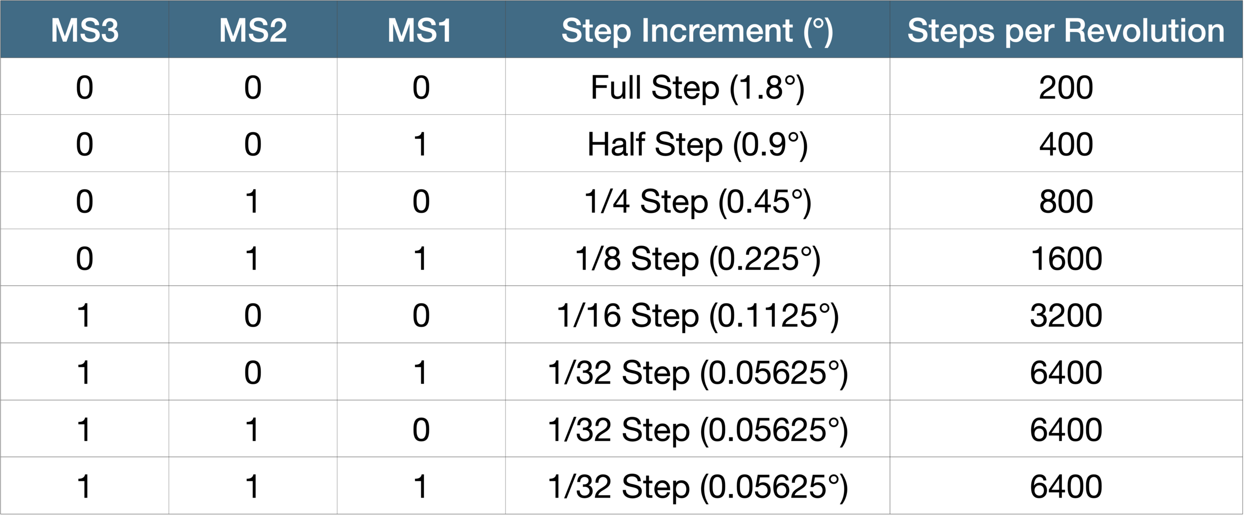
The third argument, an integer value, controls the number of steps to take during the call to the function. As an example, if the second argument is set to “1/32” and the MS1-MS3 values are all set to 1, the third argument set to 6400 will go through a 360° rotation.
The fourth argument, a float value, controls the delay between each step. This is perhaps the most sensitive parameter in the call to motor_go(), as different current settings and motors can cause different behavior based on this value. If the motor is experiencing some jittering, this value may need to be decreased. This is mostly a function of the software control of the DRV8825 (hardware control is outside the scope of this tutorial).
The fifth argument simply controls the printout of debugging information of the RpiMotorLib (sometimes called verbosity).
The sixth argument of the motor_go() function is the initial delay before the motor control begins, which can be essential when updating at high speeds, particularly when rapidly reversing the direction of the motor.
A video demonstration of the NEMA 17 being controlled by the Raspberry Pi 4 at full step rotating 200 steps around its axis, then reverses the direction and spins another 200 back in the other direction (360° in both directions):
The code to replicate the test above is given below:
#######################################
# Copyright (c) 2021 Maker Portal LLC
# Author: Joshua Hrisko
#######################################
#
# NEMA 17 (17HS4023) Raspberry Pi Tests
# --- rotating the NEMA 17 clockwise
# --- and counterclockwise in a loop
#
#
#######################################
#
import RPi.GPIO as GPIO
from RpiMotorLib import RpiMotorLib
import time

################################
# RPi and Motor Pre-allocations
################################
#
#define GPIO pins
direction= 22 # Direction (DIR) GPIO Pin
step = 23 # Step GPIO Pin
EN_pin = 24 # enable pin (LOW to enable)

# Declare a instance of class pass GPIO pins numbers and the motor type
mymotortest = RpiMotorLib.A4988Nema(direction, step, (21,21,21), "DRV8825")
GPIO.setup(EN_pin,GPIO.OUT) # set enable pin as output

###########################
# Actual motor control
###########################
#
dir_array = [False,True]
GPIO.output(EN_pin,GPIO.LOW) # pull enable to low to enable motor
for ii in range(10):
    mymotortest.motor_go(dir_array[ii%2], # False=Clockwise, True=Counterclockwise
                         "Full" , # Step type (Full,Half,1/4,1/8,1/16,1/32)
                         200, # number of steps
                         .0005, # step delay [sec]
                         False, # True = print verbose output
                         .05) # initial delay [sec]
    time.sleep(1)

GPIO.cleanup() # clear GPIO allocations after run
The NEMA 17 stepper motor, model 17HS4023, was introduced along with the DRV8825 stepper driver. The DRV8825 was wired to a Raspberry Pi 4 computer, which uses Python as the software used to control the NEMA 17 stepper motor. The Python library allows for control of specific stepper parameters such as step angle, step direction (clockwise or counterclockwise), and step delay. These parameters specify the speed and accuracy of the motor movement. The DRV8825 and stepper bridge make wiring of the NEMA 17 to the Raspberry Pi simple and easy for rapid prototyping purposes. This tutorial is meant as an introduction to using the NEMA 17 Stepper Motor Kit and interfacing the motor with a Raspberry Pi computer. In the next tutorial involving the NEMA 17, Raspberry Pi and Python will again be used to control the stepper, but with a specific application of a point cloud mapper application.

See More in Raspberry Pi and Motors: