Posts tagged Pulse-Width Modulation
An Introduction to the Raspberry Pi Pico with MicroPython

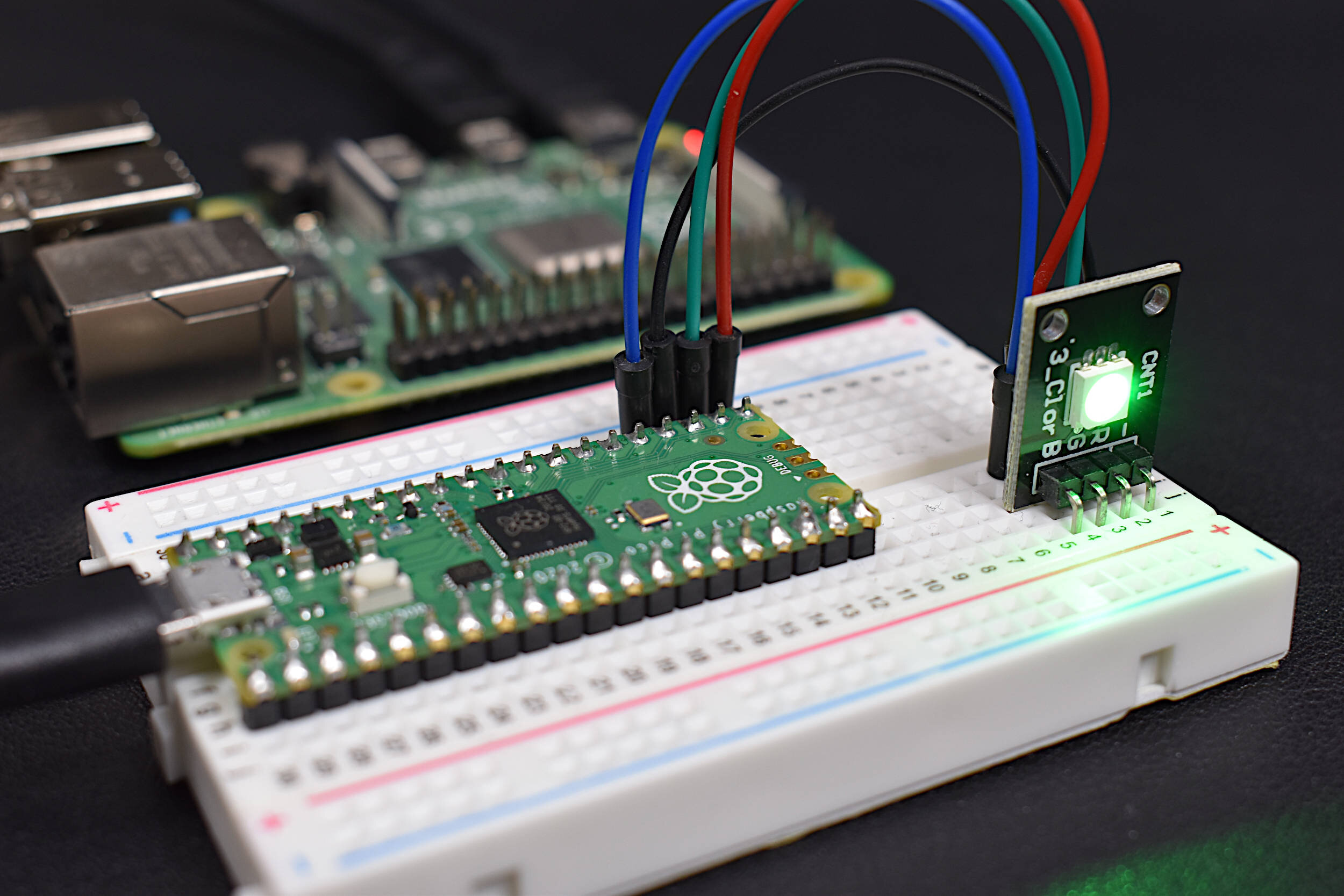
The Raspberry Pi Pico was recently released by the Raspberry Pi Foundation as a competitive microcontroller in the open-source electronics sphere. The Pico shares many of the capabilities of common Arduino boards including: analog-to-digital conversion (12-bit ADC), UART, SPI, I2C, PWM, among others. The board is just 21mm x 51mm in size, making it ideal for applications that require low-profile designs. One of the innovations of the Pico is the dual-core processor, which permits multiprocessing at clock rates up to 133 MHz. One particular draw of the Pico is its compatibility with MicroPython, which is chosen as the programming tool for this project. The focus on MicroPython, as opposed to C/C++, minimizes the confusion and time required to get started with the Pico. A Raspberry Pi 4 computer is ideal for interfacing with the Pico, which can be used to prepare, debug, and program the Pico. From start to finish - this tutorial helps users run their first custom MicroPython script on the Pico in just a few minutes. An RGB LED will be used to demonstrate general purpose input/output of the Pico microcontroller.

Read More
DIY Arduino Board

A DIY Arduino board is presented here, with most of the capabilities of the classic Arduino Uno board, but with a slimmer profile and more flexibility in hardware. The advantage to using the DIY Arduino board is its ability to change the input voltage (2.7V - 5.5V), the crystal oscillator (0-16MHz), and the use of LEDs and regulators when needed. The DIY board is capable of very lower power modes, without the requirement of draining components such as LEDs or regulators. The ATmega328P chip is at the center of every Uno board (in recent years), and is also at the center of the DIY board, which allows the DIY Arduino to behave almost identically to the Uno board.

Read More
Raspberry Pi Camera Panning with a Servo Motor

In this tutorial, the RPi is used to demonstrate pulse-width modulation (PWM) and apply it to servo motor control. Then, the servo is used to control the panning of a camera - which is also controlled by the native camera port on the Raspberry Pi. This tutorial is a simple introduction that can be expanded into a full 360° controllable camera project, or a project involving a robotic arm, or any project involving servo motors or PWM-controlled devices.

Read More
Controlling LEDs with A Multiplexer and Arduino

A demultiplexer will be used to control 8 LEDs using just 3 digital pins on the Arduino board. This method of demultiplexing frees up pins on the Arduino, but also makes control of multiple LEDs easier by consolidating the power given to each LED. This will allow us to use LEDs without resistors. In general, a demultiplexer uses N boolean outputs to control 2N switches. In our case, the CD4051 multiplexer will be used as a demultiplexer using 3 digital pins and boolean logic to control 8 individual LEDs. Several skills will also be developed, specifically with regard to programming in the Arduino programming language. Pulse-width modulation (or brightening and dimming) of LEDs will be explored, as well as randomization of LED blinks, along with the general selection process for boolean switching with the demultiplexer.

Read More