NodeMCU Tutorial Series Part I: Arduino IDE and Blinking an LED
Blog Post Index:
NodeMCU is a WiFi platform that integrates the ESP8266 system on chip hardware with the familiarities of open-source software. The NodeMCU is powerful because it endows users with the ability to create Internet of Things (IoT) projects at a relatively low cost with tools readily available and open to the maker community. NodeMCU is fully compatible with the Arduino IDE, which is the method for programming the board in this tutorial.
With the inclusion of NodeMCU, we no longer need a dedicated Arduino board. Instead, the ESP8266 SoC is fully integrated to handle microcontroller tasks so that all we need to create a WiFi-enabled node is a board and the Arduino IDE. The NodeMCU platform is inexpensive and popular, which means plentiful documentation and resources. This allows users to dive right into applications without worrying about the specifics of complex communication involved in WiFi-connected devices. If you want to read more about the specifics of NodeMCU, see one of the following resources:

This is the first entry into the exploration of NodeMCU, which will cover the board specifics, programming in the Arduino IDE, and a simple blink sketch.
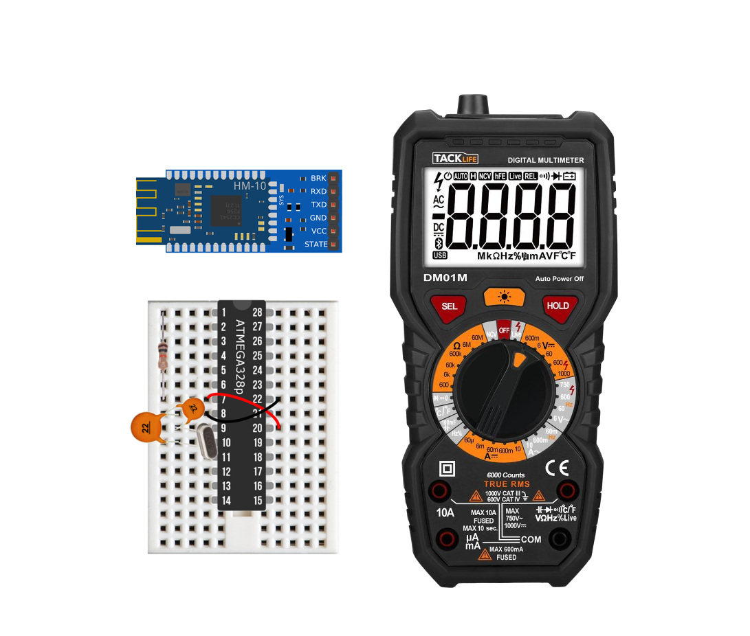
The minimum hardware components needed for getting started with NodeMCU are: a NodeMCU board and a computer capable of handling the Arduino IDE. That’s it! However, I will be using a few external components that will indicate whether the microcontroller in the NodeMCU board is functioning properly and responding to Arduino commands as we expect it to. The parts list for this tutorial is as follows (with affiliate links):
The LED will be wired to pin D1 (GPIO 5) on the NodeMCU board, which we will program later to change state with a random interval between each on and off state. A pinout diagram for the NodeMCU is shown below for reference:
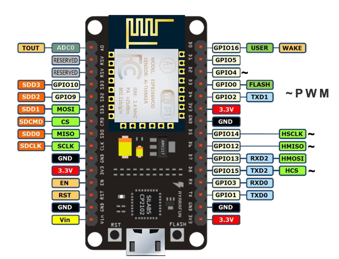
Image courtesy of: https://www.teachmemicro.com/nodemcu-pinout/
We will stick to using the available GPIO pins, but identify them with traditional Arduino D/A pins for referencing. In our case, we use D1 for GPIO 5. The wiring for the LED is shown below for D1:
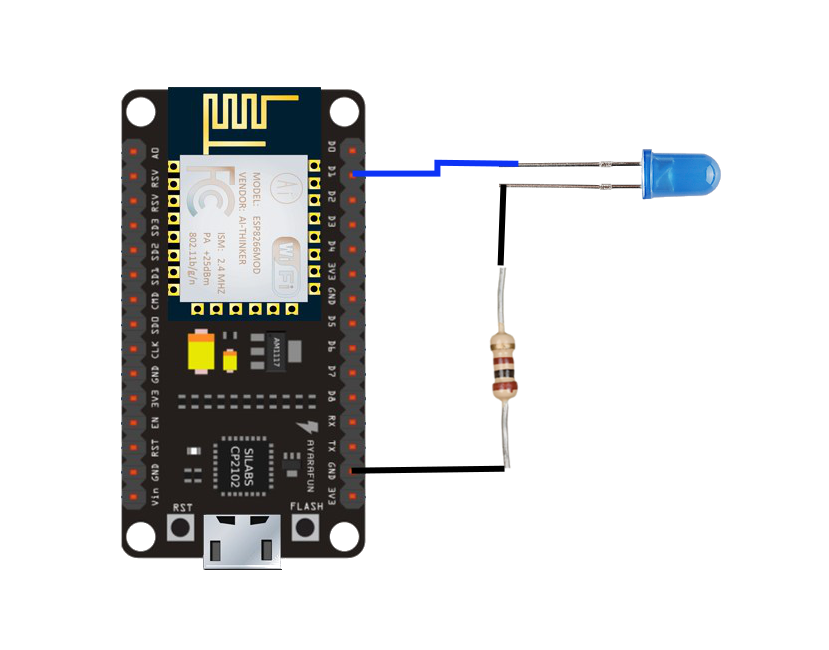
Wiring NodeMCU + LED to mimic an Arduino Board
In the next section, I will demonstrate the process involved in downloading the NodeMCU board framework onto the Arduino IDE and preparing the IDE to handle NodeMCU boards.
The ESP8266 community has spent a lot of time developing NodeMCU for the Arduino framework. Below, I outline the steps needed to download the board software for ESP8266 boards (NodeMCU) and how to program the board parameters to handle the specific NodeMCU 1.0 version referenced above.

Step 1: Go to Preferences
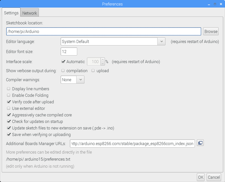
Step 2: Insert the ESP8266 package into the Additional Boards Manager URL window
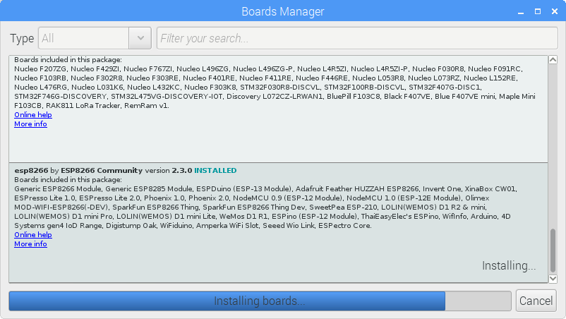
Step 3: Go to Tools-> Board -> Boards Manager… and find the new esp8266 link and install it

Step 4: Verify that the NodeMCU and ESP8266 boards are listed

Step 5: Ensure that the parameters match the selections shown to the left here
After our NodeMCU 1.0 board is selected and the parameters match those above in step 5, we can finally upload a sketch to the board and emulate an Arduino board!
Uploading a sketch to a NodeMCU board is nearly identical to any Arduino board. You program in the IDE, and select ‘Upload.’ The NodeMCU board takes a bit more time than an Uno or Nano board, but much of the programming is identical in function. In our case, we will test that the board is being properly programmed by uploading a sketch that controls an LED on digital pin 1 (D1, GPIO 5). Scroll up to look at the pinout of the NodeMCU and verify that your board looks similar and has similar markings on the pins.
Copy and paste the code below and click ‘Upload.’
void setup() {
  pinMode(D1, OUTPUT);     // Initialize the LED_BUILTIN pin as an output
}

// the loop function runs over and over again forever
void loop() {
  digitalWrite(D1, LOW);   // Turn the LED on (Note that LOW is the voltage level
  // but actually the LED is on; this is because
  // it is active low on the ESP-01)
  delay(random(300));                      // Wait for a second
  digitalWrite(D1, HIGH);  // Turn the LED off by making the voltage HIGH
  delay(random(300));                      // Wait for two seconds (to demonstrate the active low LED)
}
If everything was successful and you see ‘Done uploading’ without any errors in the IDE - then your NodeMCU as an Arduino board was successful!
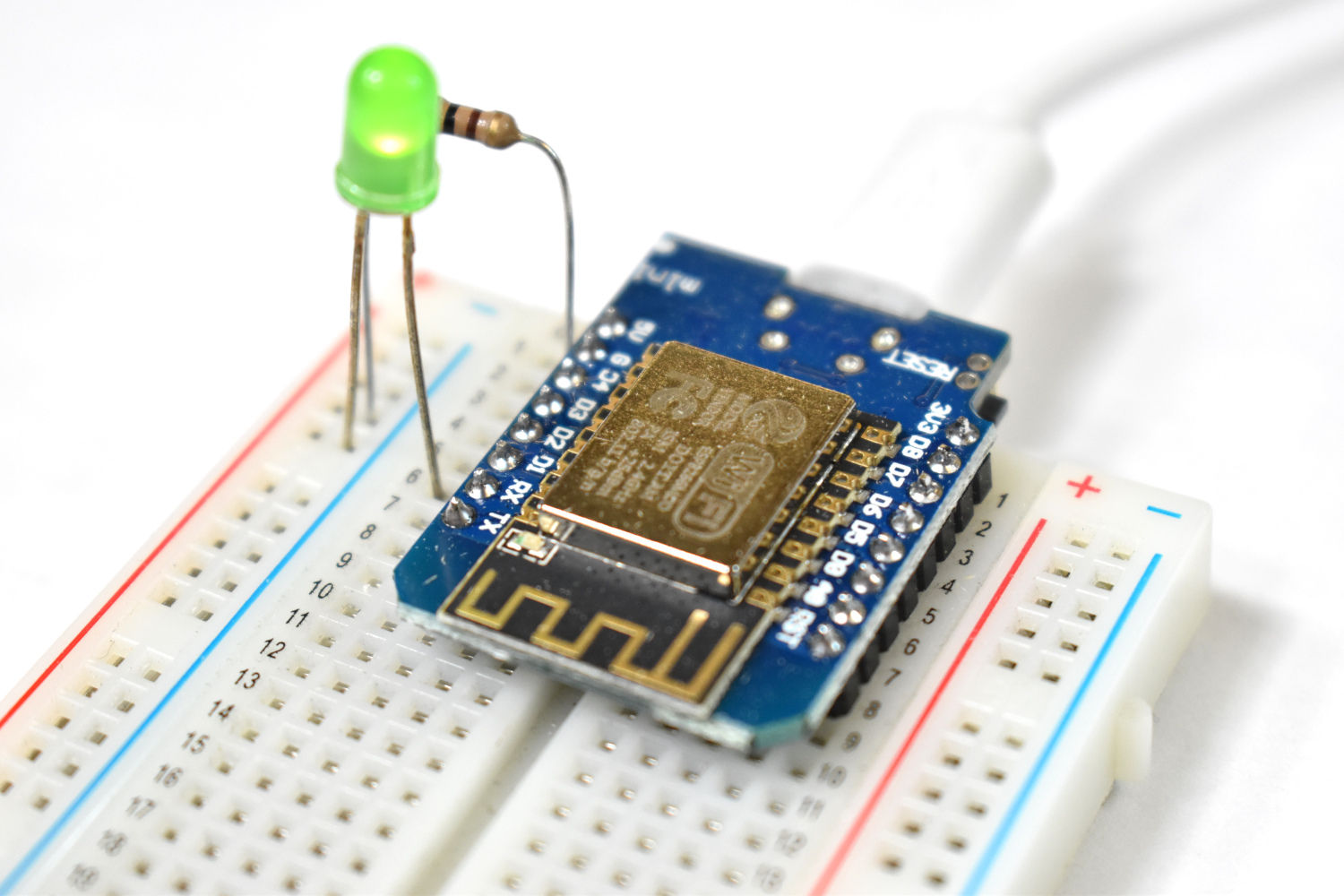
Below is what you should see from the uploaded code above:
In this entry into the NodeMCU tutorial series I introduced the NodeMCU board and programming in the Arduino IDE. I demonstrated how to wire and program a NodeMCU board like an Arduino board to control an external LED. I have only scratched the surface of the NodeMCU framework and will continue the series by exploring the WiFi capabilities of the onboard ESP8266 chip, which will allow us to create multi-functional web-based applications like sensor nodes, independent servers, and WiFi control systems - all using an inexpensive, open-source NodeMCU board used in this tutorial.

See More in NodeMCU and IoT: