NodeMCU Tutorial Series Part II: NodeMCU Server Control Over Local Area Network
Blog Post Index:
In the previous entry of this tutorial series I introduced the NodeMCU framework and demonstrated how to program one of its microcontrollers using the Arduino IDE [tutorial link here]. In this tutorial, I assume the user has a basic understanding of the NodeMCU v1.0 board and how to program it using the ESP8266 library in the Arduino IDE. This tutorial picks up where the previous left off, taking full advantage of the ESP8266 WiFi chip by serving a local webpage to control the general purpose input and output (GPIO) pins on a NodeMCU microcontroller.
Some basic HTML and CSS programming methods will be utilized to create a stylish webpage that is both asynchronous (AJAX) and input-driven - this will give the user the ability to control the pins on the microcontroller. For the current example, an electromagnet and LED will be controlled using pulse width modulation (PWM) and simple high/low logic, respectively. The PWM control allows the user to change the voltage to the component, altering the magnetic field of the electromagnet. For the LED, the traditional digitalWrite() method will turn the LED on and off.
A great deal of this tutorial will focus on the implementation of HTML methods in the NodeMCU webpage. Some exploration and knowledge of HTML and web development is recommended, but not needed for developing this project, however, a strong background in Arduino in programming is required.
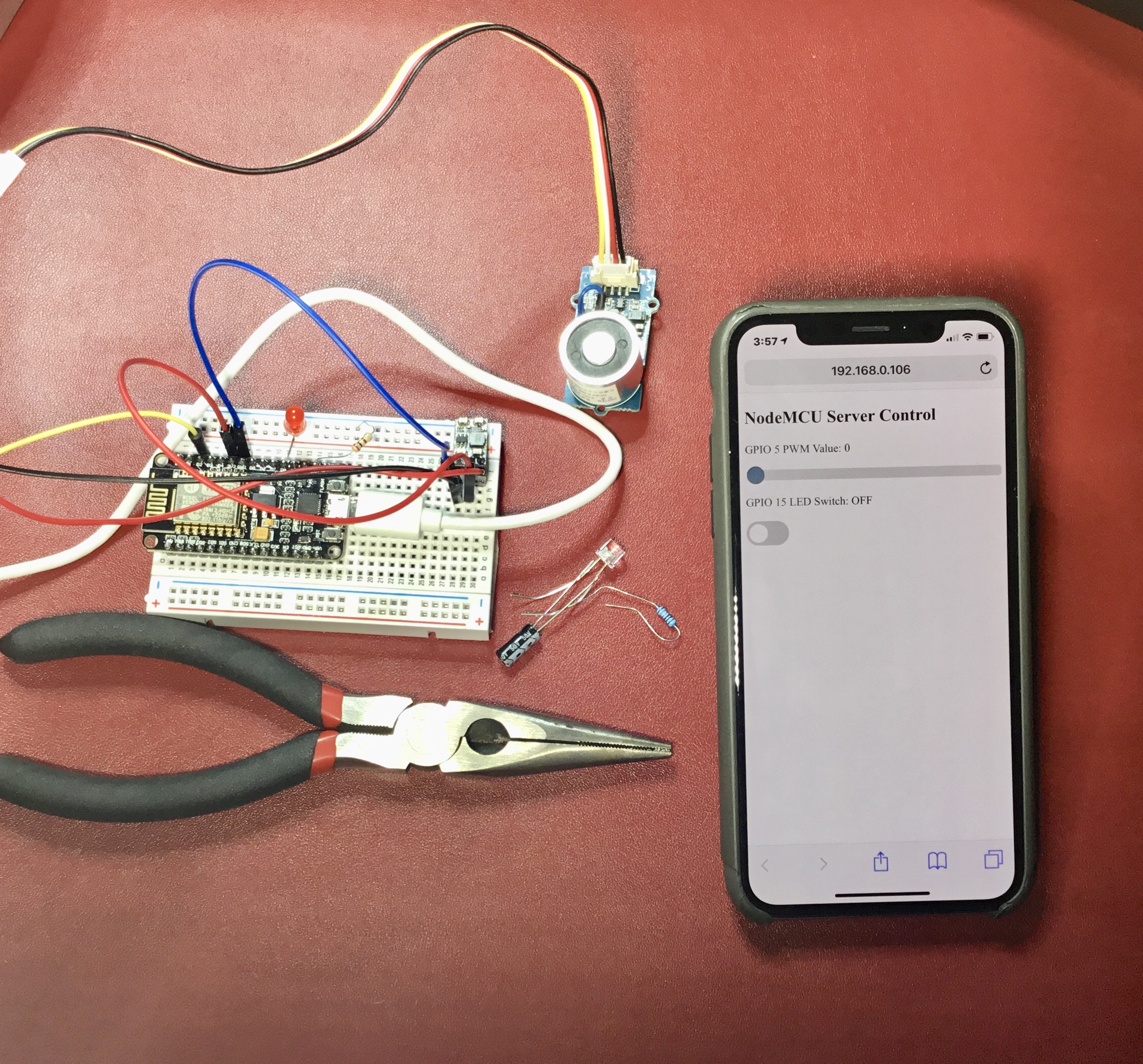
NodeMCU Setup with Webpage Control on iPhone.
The electromagnet is a relatively inexpensive and available component from electronics sources like Seeed Studio, Adafruit, and Amazon. The PWM control on the NodeMCU board has 10-bit resolution (2 bits higher than the standard Arduino PWM resolution), giving us range from 0-1023. There is one caveat to the NodeMCU, and that’s its voltage limitation at 3.3V. And since the electromagnets are almost always 5V or higher, we will use a buck converter to go from 3.3V to 5V. Along with the control components, I have listed a breadboard, jumper wires, and a resistor - standard components for LED control and prototyping. The full parts list is below:
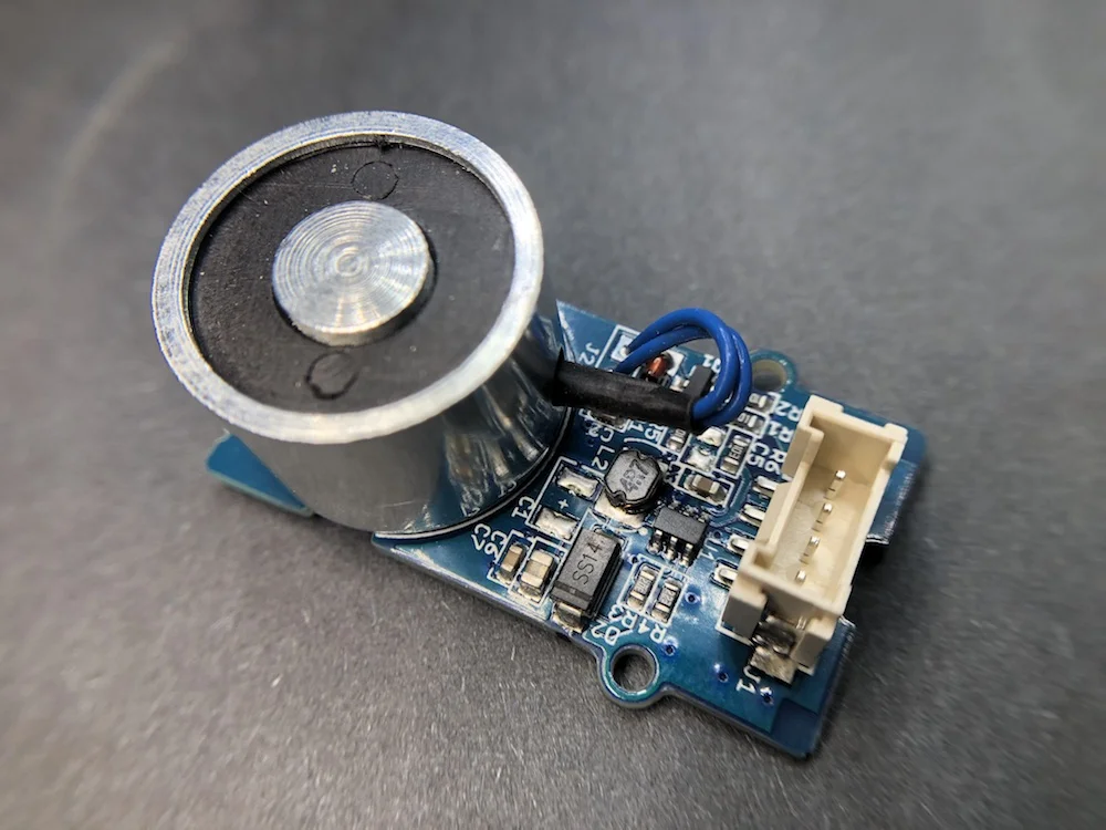
Seeed Studio Electromagnet will serve as the PWM-controlled component from the WiFi server.
After gathering the required parts, we need to decide which pins we can and want to use for the control sequences. Since the project requires the use of PWM, we are restricted to GPIO pins 4, 12, 13, 14, 15. Other pins may be capable of handling PWM depending on board version, but I will stick to the pinout which corresponds to the board I’ll be using (shown below).
NodeMCU v1.0 Board Pinout [Image courtesy of: https://www.teachmemicro.com/nodemcu-pinout/]
I have arbitrarily used GPIO4 as the PWM pin and GPIO 15 as the output pin for the LED switch. The wiring is shown below:

Wiring for NodeMCU Server Control
In the next section I will introduce the full code for controlling both the electromagnet (via PWM) and the LED. The codes are fairly involved in both NodeMCU jargon and HTML code, so I recommend copying and pasting as is, then altering after verifying that everything functions as expected. A large portion of the difficulty of working with NodeMCU is understanding the WiFi and HTML side of things, not the microcontroller side.
The code below should be uploaded to the NodeMCU board via the Arduino IDE. Be sure that the ESP8266 library is downloaded and the correct options are selected under the board parameters in the IDE.
#include <ESP8266WiFi.h>
#include <WiFiClient.h>
#include <ESP8266WebServer.h>

#include "pwm_slider_button.h" // file where html page is written

#define STASSID "ABC-123" // name of router
#define STAPSK  "pwd_56789" // pwd for router

#define PWM_pin 4  // PWM pin
#define button_pin 15 // button pin for LED etc.

const char* ssid = STASSID;
const char* password = STAPSK;

ESP8266WebServer server(80); // port 80 (standard)

// prints out main page with pwm slider and button etc...

void handle_root() {
 String root_code = html_page; // html code from .h file
 server.send(200, "text/html", root_code); // upload code to show webpage
}

// handling button press on webpage

void handle_button() {
 String button_state = server.arg("button_state"); // on page ./setButton we are reading the variable 'button_state'

 String curr_state = "OFF"; // for sending back to the page
 if(button_state == "1")
 {
  digitalWrite(button_pin,HIGH); //LED ON
  curr_state = "ON";
 }
 else
 {
  digitalWrite(button_pin,LOW); //LED OFF
  curr_state = "OFF";
 }

 server.send(200, "text/plane", curr_state); //Send state back to page
}

// handling PWM:

void handle_pwm() {
 String pwm_val = server.arg("PWMval"); // reading from slider on html pagae
 Serial.print("slider val: ");
 Serial.println(pwm_val);
 analogWrite(PWM_pin,pwm_val.toInt()); // chaning the value on the NodeMCU board
 server.send(200,"text/plane","0"); // handling the webpage update
}


// setup for server and NodeMCU pins

void setup(void){
  Serial.begin(115200);

  WiFi.begin(ssid, password);     //Connect to your WiFi router using ssid and pwd given above
  Serial.println("");

  // choose output for both PWM and button pins
  pinMode(PWM_pin,OUTPUT);
  pinMode(button_pin,OUTPUT);

  // Connection wait
  while (WiFi.status() != WL_CONNECTED) {
    delay(500);
    Serial.print(".");
  }

  // print some parameters pertaining to server IP etc.
  Serial.println("");
  Serial.print("Connected to ");
  Serial.println(ssid);
  Serial.print("IP address: ");
  Serial.println(WiFi.localIP());  // IP address given to NodeMCU

  server.on("/", handle_root);      // primary page where html from .h file will be shown
  server.on("/setPWM", handle_pwm); // handles the PWM values
  server.on("/setButton", handle_button); // handles button values

  server.begin();                  // begin server
  Serial.println("HTTP server started");
}

// loop for constant update of server pages
void loop(void){
  server.handleClient();          //Handle tapping of buttons and sliders
}
The majority of the Arduino code is formality with the traditional library imports, preallocations, and setup() and loop() functions. Beyond the standard code, there is an instantiation of the ESP8266 called ‘server’ - and this is where the majority of the handling is done. The server houses the interactivity between the webpage and the NodeMCU microcontroller. Thus, it is the most important and pivotal part of working with the NodeMCU board.
For example, the following lines of code setup three separate pages for handling data and interactivity with the server:
server.on("/", handle_root);      // primary page where html from .h file will be shown
server.on("/setPWM", handle_pwm); // handles the PWM values
server.on("/setButton", handle_button); // handles button values
In practice, on the PWM page ("/setPWM"), we look to its corresponding function handle_pwm() to listen for a change in variable called "PWMval", which is changed when the PWM slider is changed on the web page. In the code below we are taking the new value of the PWM slider, and using 'analogWrite()' to update the PWM pin on the NodeMCU microcontroller, consequently changing the value of the electromagnet's magnetic field:
void handle_pwm() {
 String pwm_val = server.arg("PWMval"); // reading from slider on html pagae
 Serial.print("slider val: ");
 Serial.println(pwm_val);
 analogWrite(PWM_pin,pwm_val.toInt()); // chaning the value on the NodeMCU board
 server.send(200,"text/plane","0"); // handling the webpage update
}
This is the method that should be used for any desired control from a NodeMCU web page. In the next section, I will discuss the server-side HTML, which creates the interaction and updates seen by the human interacting with the web page.
A large portion of the HTML code in the web page contains style lines that are not particularly necessary for understanding the communication between the web page and microcontroller. The full code is below:
const char html_page[] PROGMEM = R"=====(
<!DOCTYPE html>
<html>
<head>
<meta name="viewport" content="width=device-width, initial-scale=1">
<style>
.slidecontainer {
  width: 100%;
}

.slider {
  -webkit-appearance: none;
  width: 100%;
  height: 15px;
  border-radius: 5px;
  background: #d3d3d3;
  outline: none;
  opacity: 0.7;
  -webkit-transition: .0s;
  transition: opacity .2s;
}

.slider:hover {
  opacity: 1;
}

.slider::-webkit-slider-thumb {
  -webkit-appearance: none;
  appearance: none;
  width: 25px;
  height: 25px;
  border-radius: 50%;
  background: #326C88;
  cursor: pointer;
}

.slider::-moz-range-thumb {
  width: 25px;
  height: 25px;
  border-radius: 50%;
  background: #326C88;
  cursor: pointer;
}

/* Rounded switch */

.switch {
  position: relative;
  display: inline-block;
  width: 60px;
  height: 34px;
}

.switch input {
  opacity: 0;
  width: 0;
  height: 0;
}

.slider1 {
  position: absolute;
  cursor: pointer;
  top: 0;
  left: 0;
  right: 0;
  bottom: 0;
  background-color: #ccc;
  -webkit-transition: .4s;
  transition: .4s;
}

.slider1:before {
  position: absolute;
  content: "";
  height: 26px;
  width: 26px;
  left: 4px;
  bottom: 4px;
  background-color: white;
  -webkit-transition: .2s;
  transition: .2s;
}

input:checked + .slider1 {
  background-color: #326C88;
}

input:focus + .slider1 {
  box-shadow: 0 0 1px #326C88;
}

input:checked + .slider1:before {
  -webkit-transform: translateX(26px);
  -ms-transform: translateX(26px);
  transform: translateX(26px);
}

.slider1.round {
  border-radius: 34px;
}

.slider1.round:before {
  border-radius: 50%;
}

</style>
</head>
<body>

<h2>NodeMCU Server Control</h2>

<div class="slidecontainer">
  <p>GPIO 5 PWM Value: <span id="slider_p"></span></p>
  <input type="range" min="0" max="1023" value="0" class="slider" id="myRange">

<p>GPIO 15 LED Switch: <span id="led_state">OFF</span></p>
<label class="switch">
  <input type="checkbox" onchange="state_change(this)">
  <span class="slider1 round"></span>
</label>
</div>

<script src="https://canvasjs.com/assets/script/canvasjs.min.js"></script>


<script>
var slider = document.getElementById("myRange");
var output = document.getElementById("slider_p");
output.innerHTML = slider.value;

slider.onchange = function() {
  output.innerHTML = this.value;
  pwm_change(this.value);
}
</script>

<script>
function pwm_change(val) {
  var xhttp = new XMLHttpRequest();
  xhttp.open("GET", "setPWM?PWMval="+val, true);
  xhttp.send();
}
</script>

<script>
function state_change(element) {
  var xhttp = new XMLHttpRequest();

  if (element.checked){
    xhttp.open("GET", "setButton?button_state=1", true);
    document.getElementById("led_state").innerHTML = "ON";
  } else if (!element.checked){
    xhttp.open("GET", "setButton?button_state=0", true);
    document.getElementById("led_state").innerHTML = "OFF";
  }
  xhttp.send();
}
</script>

</body>

</html>
)=====";
The primary functionality occurs in the <body> of the HTML file, where the headers and <div> lines occur. In our case, we use an input range slider from 0-1023 (to match the 10-bit resolution) for the electromagnet and a simple checkbox switch for turning the LED on and off. Below is the code series in the HTML <body> where the interactive controls exist. Notice the classes involved with each component in the code.
<h2>NodeMCU Server Control</h2>

<div class="slidecontainer">
  <p>GPIO 5 PWM Value: <span id="slider_p"></span></p>
  <input type="range" min="0" max="1023" value="0" class="slider" id="myRange">

<p>GPIO 15 LED Switch: <span id="led_state">OFF</span></p>
<label class="switch">
  <input type="checkbox" onchange="state_change(this)">
  <span class="slider1 round"></span>
</label>
</div>
Let's inspect the following line:
<input type="checkbox" onchange="state_change(this)">
The code waits for the user's input and calls the function state_change(element). The function is as follows:
function state_change(element) {
  var xhttp = new XMLHttpRequest();

  if (element.checked){
    xhttp.open("GET", "setButton?button_state=1", true);
    document.getElementById("led_state").innerHTML = "ON";
  } else if (!element.checked){
    xhttp.open("GET", "setButton?button_state=0", true);
    document.getElementById("led_state").innerHTML = "OFF";
  }
  xhttp.send();
}
At this point, I have demonstrated the wiring, programming, and functionality of the NodeMCU server for PWM and simple digitalWrite() processes. After uploading the Arduino code to the NodeMCU board and ensure everything was successful, we must test that the code and board are functioning properly and as expected. We can do this by first opening the serial port on the Arduino IDE and identifying the IP address of the NodeMCU ESP8266 WiFi server. You should see a printout that looks similar to the text below:
Connected to ABC-123
IP address: 192.168.0.15
HTTP server started
This lets the user know several things:
Which WiFi network the ESP8266 is connected to
The IP address on the network
Whether the server has started or not
Now the user can open a device on the WiFi network and type in the server IP address above. The page loaded should be identical to the one shown below:
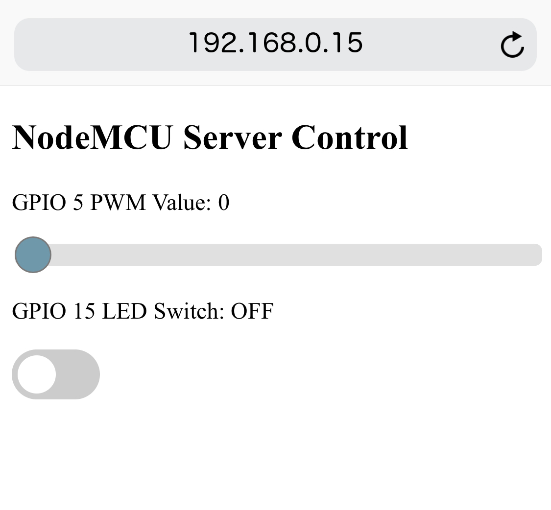
After verifying the visual layout, the user should test the server for functionality with some LEDs to be certain both the PWM and on/off are operating properly. Below is a demo video of the server with an iPhone over a local area network. It shows the LED turning on and off with the GPIO 15 switch, and it also shows the PWM working for the electromagnet, which is able to pick up certain objects with differing amount of modulation off the PWM slider.
This tutorial continued the discussion and implementation around the NodeMCU framework within Arduino. During the article, I outlined several methods on the Arduino end and server-side for controlling the NodeMCU microcontroller. I used PWM to modulate the strength of an electromagnet while also using a simple switch to turn an LED on and off. I only briefly discussed the HTML and programming methods involved in server communication, but introduced enough so that the user can edit and alter Arduino and HTML code to produce their desired effect. This tutorial was the second in a series of tutorials where I explore the power and capabilities of the NodeMCU framework, and this tutorial was focused on WiFi server control methods. One may desire to alter the controls used here to fit their own needs whether it be in robotics, or home automation - the applications are limitless. The primary objective was to create a communicating framework with live-updating web inputs to control the microcontroller, which we were able to do with a little knowledge of Arduino, HTML, and some javascript.
In the next entry, we will explore data acquisition and visualization methods, which essentially inverts the methods shown here by reading in data from the NodeMCU microcontroller and updates a web page using that data. For the first entry into the series, see the link below!

Setup showing electromagnet, NodeMCU, and LED used in this tutorial for server-side control of the NodeMCU Arduino WiFi board.
See More in NodeMCU and IoT: