Arduino Wall-Penetrating Motion Sensor Using The RCWL-0516 Microwave Radar Module
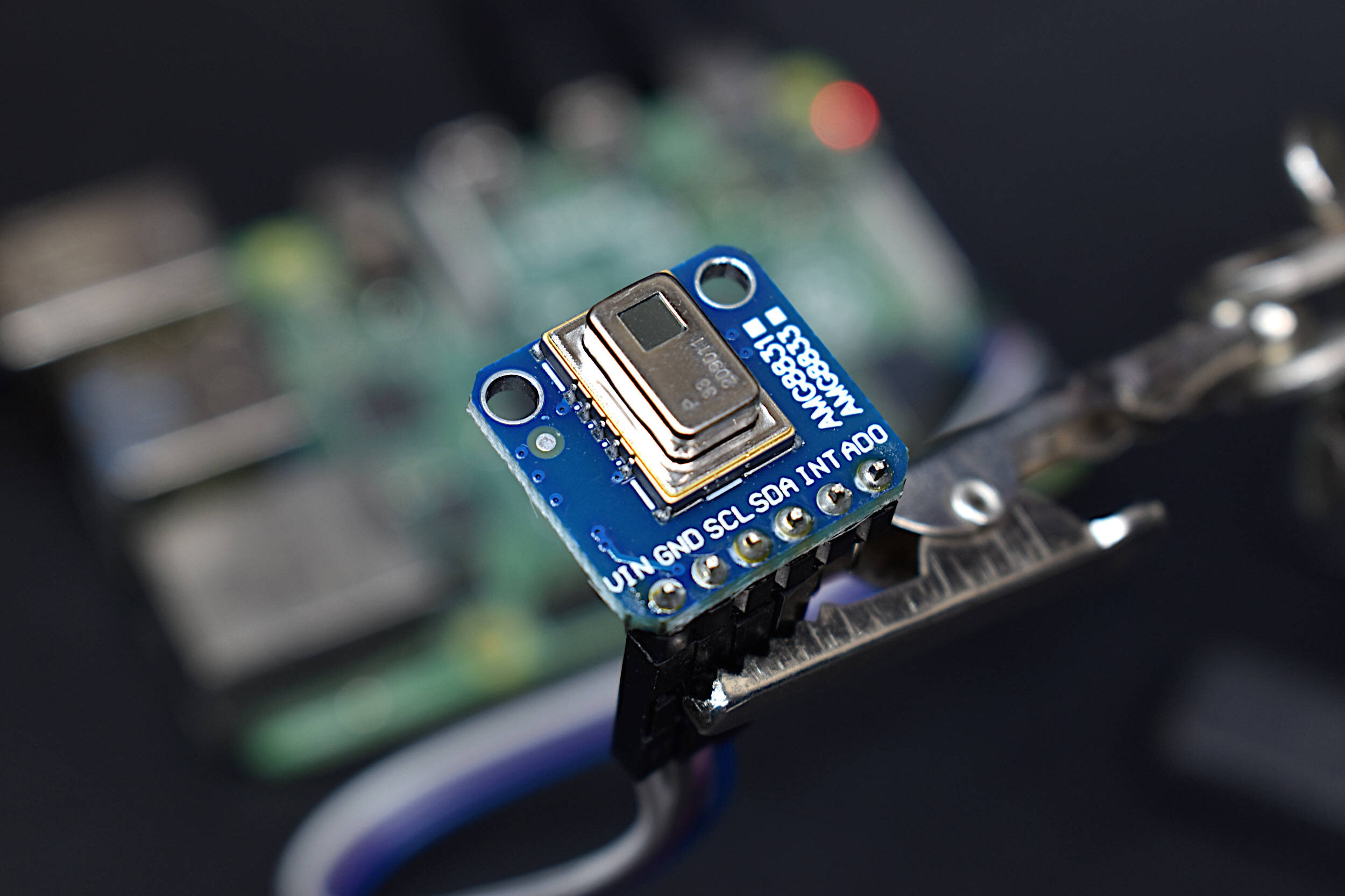
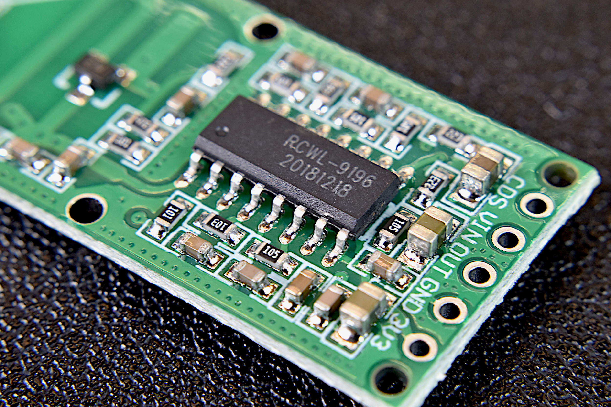
The RCWL-0516 is a microwave sensor that uses doppler technology in the 3.2GHz range to detect the motion of nearby moving objects. The onboard signal processing chip, RCWL-9196, uses the difference between the emitted frequency and the reflected frequency to notify whether there is motion surrounding the module or not. Below is a quick overview of doppler radar technologies and how they work, along with a tutorial on using the RCWL-0516 with an Arduino board to sense motion both in open air and through walls. The power of the RCWL-0516 comes in its ability to measure motion regardless of radiation (unlike a PIR sensor that measures infrared radiation). The microwave motion sensor is great for situations where exposed sensors may not be safe or scenarios where motion of all kinds is desired, not only radiating bodies.
Doppler Radar Technology
The general doppler equation for waves in a medium (non-relativistic) can be written as the following:
where is the observed frequency,
is the speed of waves in the medium,
is the velocity of the receiver (moving object),
is the velocity of the source (emitter), and
is the frequency being emitted from the source.
In our case, we assume a stationary source and investigate the reflected frequency measured back at the source. This is the method used by doppler radars to determine position, speed, and angle of moving aircraft and even planets and stars in the galaxy. The derivation for this equation is quite involved (since we must use relativistic methods when solving for electromagnetic waves like microwaves). Resources can for doing so can be found at the following:
The electromagnetic doppler radar equation can thus be written as follows:
where the velocity, , has been repeated using the stationarity assumption, which includes the reflected shift. The observed frequency,
, is the frequency measured back at the source. This also means that if the object is moving away from the source, the velocity would be negative - resulting in a lower observed frequency. A diagram for the moving doppler system in shown in Figure 2.

Figure 2: Doppler radar observation frequency for electromagnetic waves. This frequency is used to calculate the approximate speed of a moving object.
From here, we are interested in the difference between the source frequency and the frequency reflected back to the source after the wave hits the moving object. This difference (doppler shift) can be derived as follows:
And for small object velocities, we can make the following rearrangement to prepare for a Taylor series expansion:
Assuming and taking the first term in the Taylor Series expantion for
, we get:
In the case of motion sensing, we are interested in moving objects, which means we want to investigate the changes in velocity:
The equation above allows the user to set a threshold for and create a motion sensor based on the doppler radar shift received by the sensor - assuming
(speed of light) and
(microwave pulse frequency) are constant.
In the case of the RCWL-0516, the onboard signal processing chip handles the frequency shifting and notifies the user (via TTL) when a threshold has been crossed, indicating motion.
Parts List

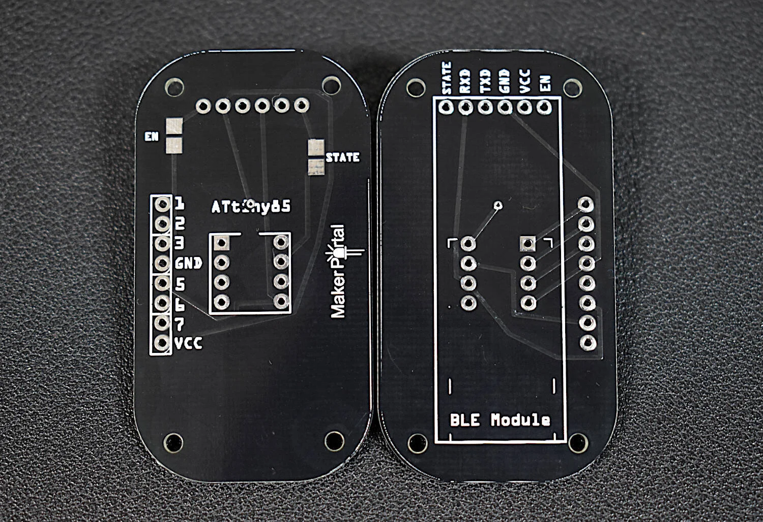
Arduino Setup and Wiring
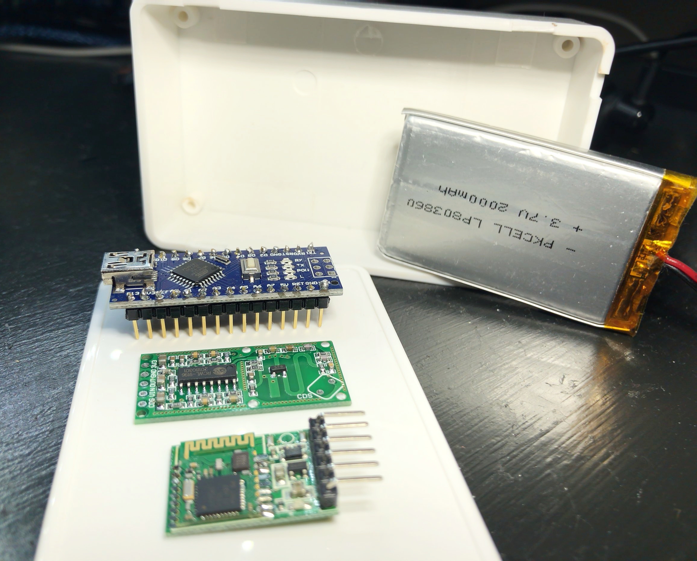
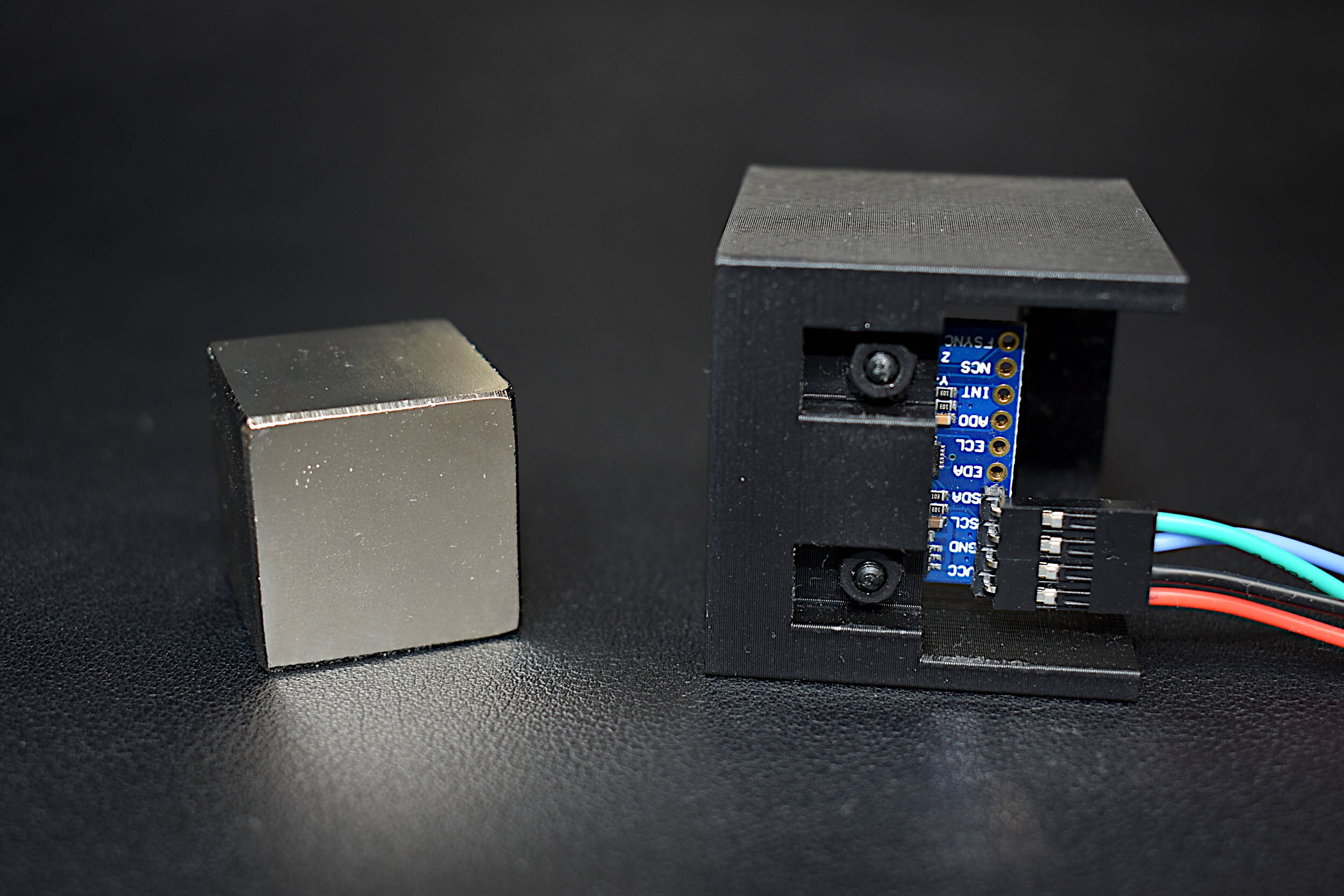
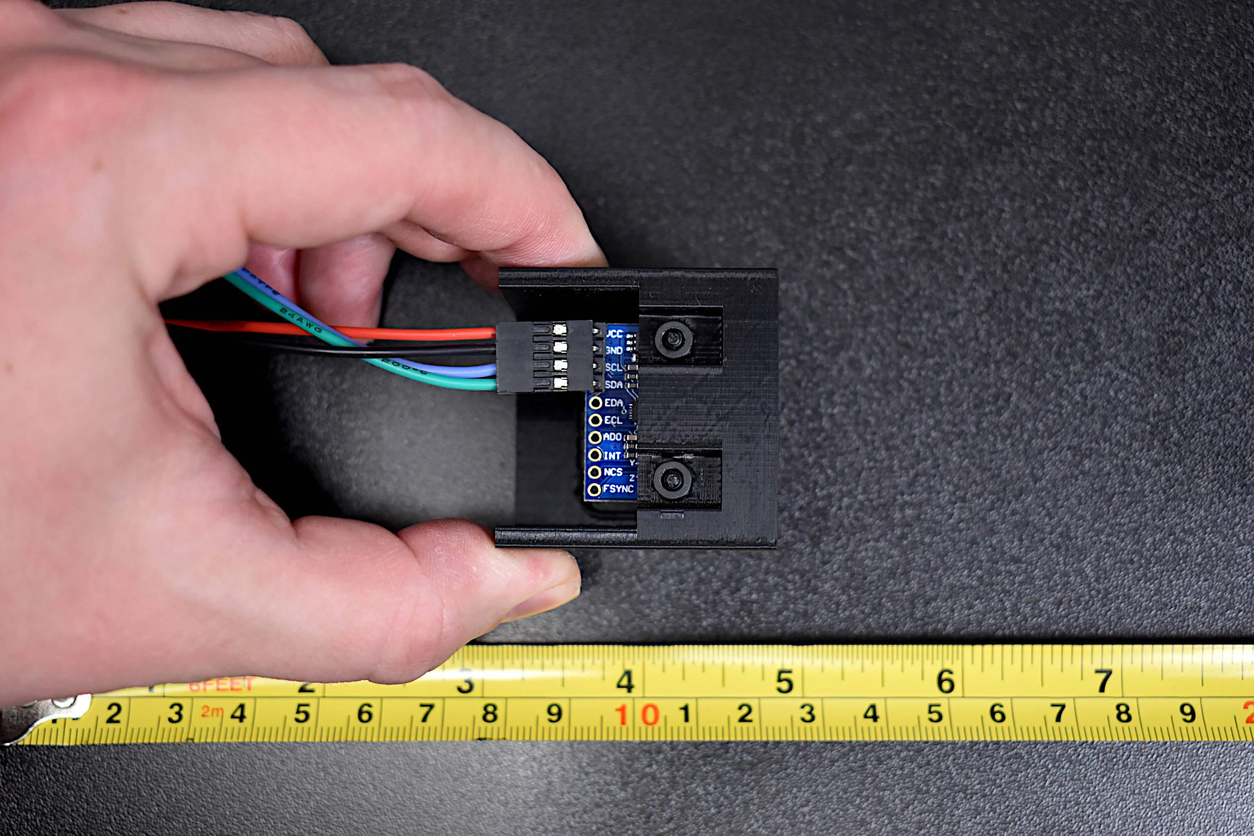
The setup for this project is quite simple - it involves wiring a Bluetooth module and the RCWL-0516 to an Arduino Nano board. I'm also using a 3.7V LiPo battery for a slimmer profile that can fit inside a small project box. The wiring diagram for my setup is shown below.
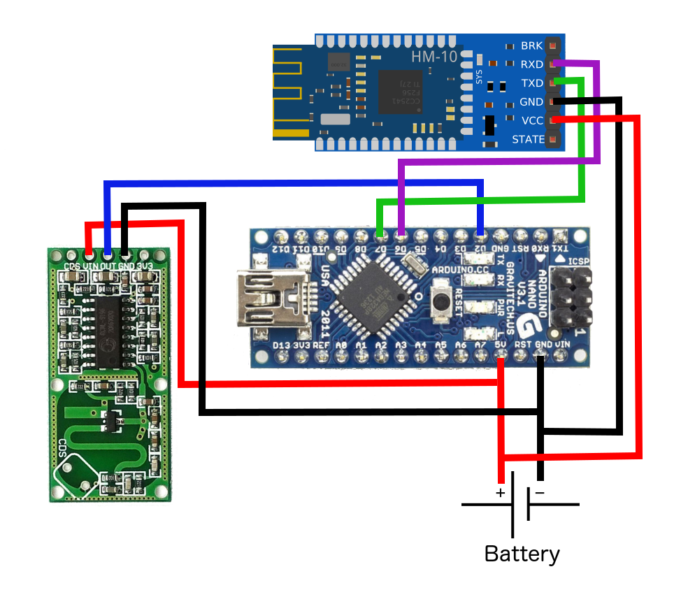
Wiring Diagram
Arduino | Sensor Pin
5V | VIN (RCWL) / VCC (HM-10)
GND | GND (RCWL) / GND (HM-10)
D2 | OUT (RCWL)
D6 |RX (HM-10)
D7 |TX (HM-10)
Arduino Code
BLE Scanner 4.0 App
After uploading the Arduino sketch to your board, it should be transmitting data via Bluetooth Low Energy (BLE). In order to read the data, be sure to either listen for the device on your Raspberry Pi, smartphone or other BLE-enabled device able to read your particular BLE module. I use the BLExAR app on the iPhone to read the data, which was developed by our team. I also use a Raspberry Pi to read BLE modules and record the data (motion). I demonstrate how to do this in a previous tutorial [here].
Conclusion
This tutorial covers both the theoretical basics of doppler radar frequency shifting and an application with Arduino that enables the user to sense motion through walls and other materials. Although the RCWL-0516 microwave module does not allow direct handling of the frequency information, the Arduino sensor demonstrates the capabilities of the microwave technology. The power of the doppler shift allows technology to approximate information about traveling objects simply by analyzing the return frequency. Many applications from the one above (motion sensing) to police radar and even airplane localization utilize this frequency shift. In the motion sensing case above, it is just a simple case of the true capabilities of frequency shifting using microwaves, and perhaps in the future I will investigate a more in-depth case using true frequency shifted information.
See More in Engineering: