Induction-Powered Wireless LED Light Bulb Using Qi Charger Parts
Wireless charging remains a mystery for many because of its slow integration into smart phones and watches. In actuality, the scientific foundation of the technology, electromagnetic induction, was founded in the early 1800s by Faraday and Henry. So if the physics is a few centuries old, what has taken the application so long? In short - it's the distance between charger and receiver coils. The proximity between the two coils creates a duality between efficiency and convenience, which means that higher efficiency requires that the coils be placed very close to one another; while more convenient arrangements, i.e. the ability to place the coils farther apart - results in decreased efficiency.
A widespread application of wireless charging does exist. It's called the Qi (pronounced, chee) standard. Qi chargers follow rules about EMF emission, foreign device interference, and efficiency, and have become somewhat of a standard in the tech world. Qi devices use inductive coupling (read about it here) to create the wireless charging used in many smartphones. Since the standard takes care of both receiver and transmitter functionality - both are widely available on the market.
In this tutorial, I will explain how I used inductive coupling (Qi TX/RX) to create a wireless LED light bulb.
Parts List
Parts List
The essential parts for this project are the Qi TX/RX, LEDs, and charger module (TP4056). With those four parts, you can recreate the wireless light effect, but with the assembly of all the parts, you can make the full light bulb. From here forward, I will assume all the parts above are available (as well as a soldering iron, rotary tool, and hot glue gun).
Assembly and Step-by-Step Instructions
Step 1.
Cut off the bottom of the light bulb and clear the contents (carefully) from inside the bulb. You will also need to make a clearing for the LEDs. I use a scissor to chip away at the glass (see Figures 1 & 2).
Figure 1: light bulb after cutting the bottom off with a scissor.

Figure 2: Cleared contents from the light bulb. A path has also been cleared for the LEDs.
Step 2.
Solder a group of LEDs in parallel (keep voltage, divide current). Be sure to keep them close together but staggered as to allow them to easily enter the hole you made in the bottom of the light bulb. Once the LEDs are soldered, ensure they fit into the bulb nicely (see Figure 3 for reference).
Figure 3: Parallel LEDs placed inside the light bulb.
Step 3.
Next, we need to solder the LED wires to the charger module (TP4056). It is imperative that the polarity is correct for the LEDs, otherwise they will not work. The long leg should be wired to the positive terminal on the TP4056, and short leg to negative. Figures 4 & 5 show the soldered TP4056 and LED leads. Figure 5 also shows the Qi receiver pad attached to the TP4056, which can be connected for testing.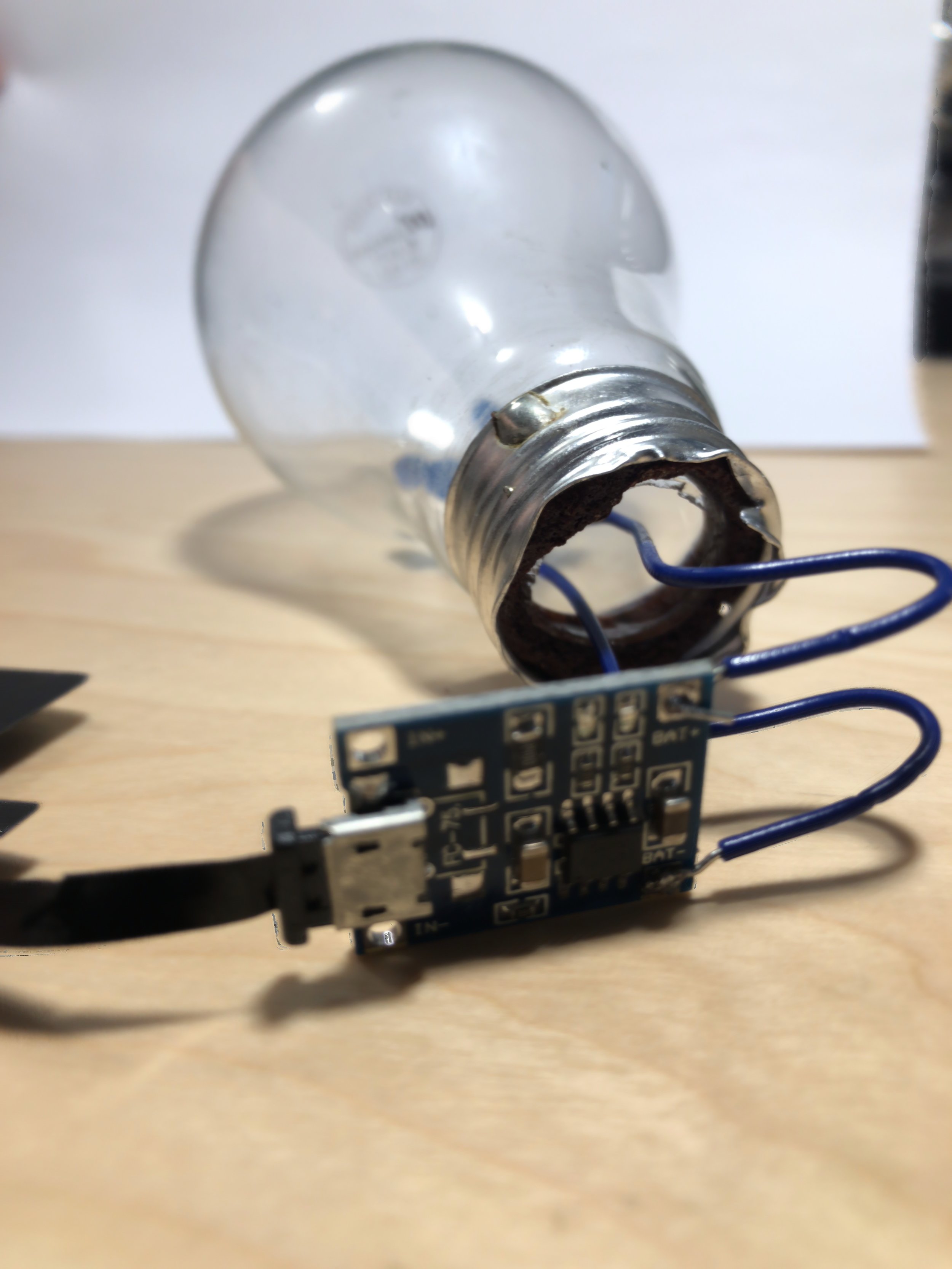
Figure 4: TP4056 charger module soldered to the LED leads.

Figure 5: The charger pad can be attached to the preliminary setup to test the LEDs, charge pad, and charge module.

At this point, the LEDs should be tested with the charge module (TP4056), Qi receiver pad, and Qi charger base. If the seutp isn't working - SOMETHING IS WRONG.
Step 4.
Now that everything is has been tested and is working as desired, we need to alter our project enclosure to make space for the base of the light bulb. At this point I also used a hot glue gun to keep the LED leads in place. Figure 6 is a photo of the enclosure I used (the one listed above in the parts list). Figure 7 shows the project box after I used my rotary tool to make a hole for the light bulb base.
Figure 6: Project box.

Figure 7: Project box after using a rotary tool to create a hole for the light bulb base. This photo also shows the TP4056 soldered to the LED leads, and the Qi charging pad as well.
Step 5.
Secure any loose parts. I used a hot glue gun to glue the Qi charging pad to the bottom of the enclosure. I also glued the LED lead wires to the light bulb base.

Project Complete!
See More in Engineering: